Using ESPHome on Sonoff RF Bridge

In a previous article, I showed you how to flash Tasmota to a Sonoff RF Bridge, which allows you to receive and transmit 433MHz RF signals like the ones used in TV remotes or many home security/alarm devices and sensors. This time we are looking at how to use ESPHome on the Sonoff RF Bridge.
Why ESPHome on Sonoff RF Bridge?
Using Tasmota on the RF bridge works well with no modifications required, but there is an issue with it – speed. In my experience (and other users I found) there was a noticeable delay between the sensor triggering and it being picked up by Tasmota.
I’m talking around a 1 second delay, which admittedly does not seem like much. However, I was using a hacked together Raspberry Pi to do the same function previously and the delay in my motion lights coming on was really noticeable compared to what it was before.
Using ESPHome, this delay is eliminated completely and it works extremely well.
Guide
Introduction
We are going to have to make a few physical modifications to the Sonoff RF Bridge in order to get ESPHome to function correctly. These modifications are not reversible (unless you are very skilled) and will make your RF Bridge unable to work with Tasmota or the stock firmware again. They could also damage the device so be careful.
Having said that, these are very inexpensive devices and the modifications are pretty simple.
It should be said I want to give full credit to the ESPurna project for documenting how to make the hardware modifications portion of this guide. The information is here.
Why are we making these modifications?
The reason we are modifying the Sonoff RF Bridge is so that ESPHome can bypass the EFM8BB1 auxiliary microcontroller that is used to encode and decode the RF signals. This allows ESPHome to directly interact with the ESP8266 chip for encoding and decoding.
Parts List
You will need the following:
- Sonoff RF Bridge
- 2 x 270 Ohm resistors (anything between 100-600 Ohm should work)
You will also need a soldering iron.
Identifying RF Bridge Models
There are two main revisions of the Sonoff RF Bridge, R1 v1.0/v2.0 and R2 v1.0. These boards have slightly different PCB layouts that you need to be mindful. I do not have an image of the R1 board but the ESPurna website has a great comparison image:
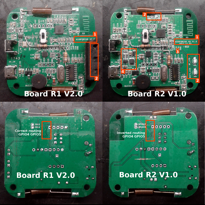
The main thing to bear in mind when making this modification is:
- The R1 board labels the pinout as: 3v3, IO5, IO4, GND – this is correct. If you have the R1 board, follow this layout.
- The R2 board labels the pinout as: 3v3, IO5, IO4, GND – this is incorrect, IO4 and IO5 are the other way around. The correct pinout from left to right is: 3v3, IO4, IO5, GND. Please keep that in mind when making these modifications.
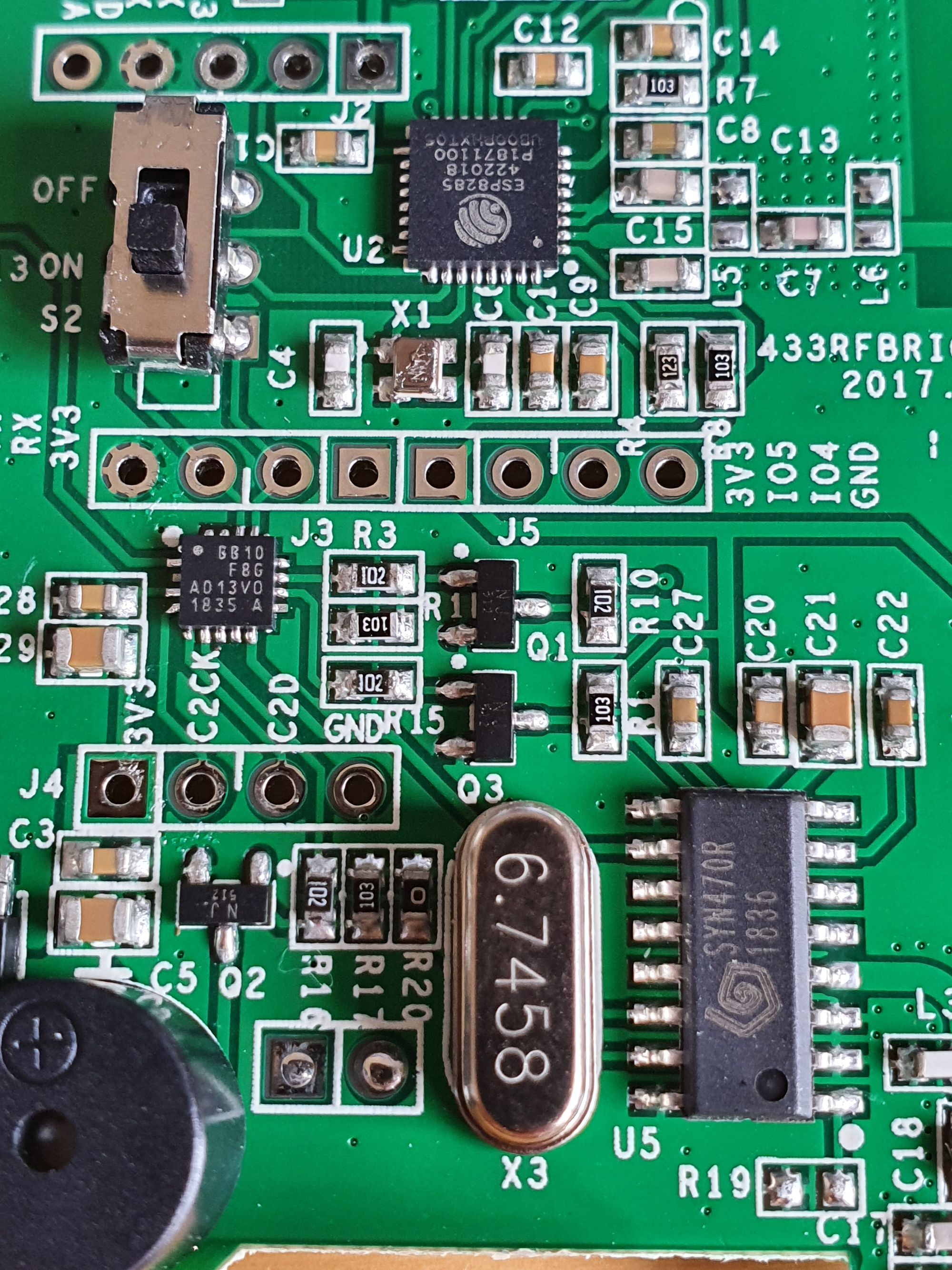
Here is a closeup of the GPIO pinout row:
Modifying the receiver signal
We are going to rewire the receiver signal first. This involves connecting GPIO4 to pin 10 of the UHF receiver.
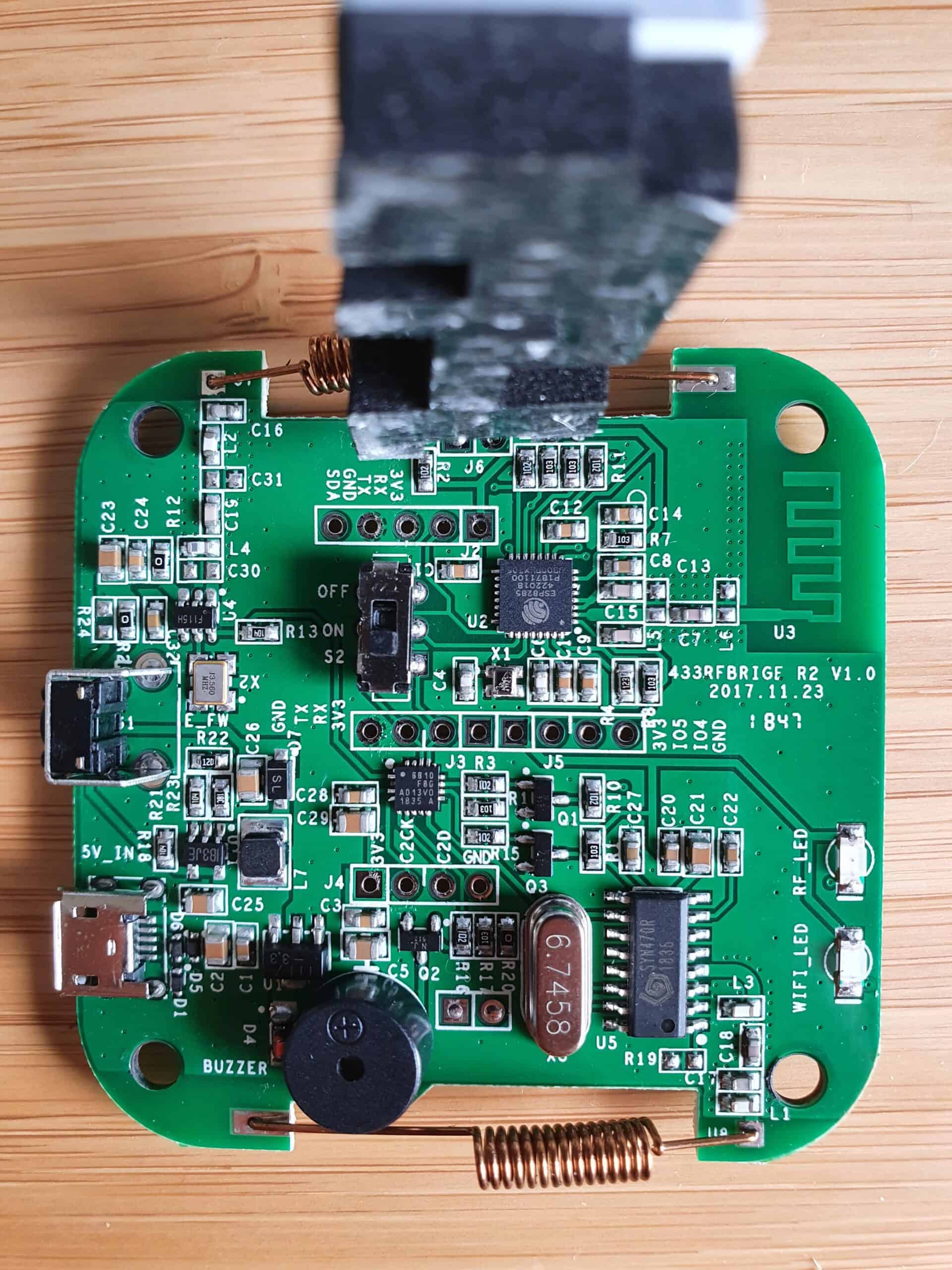
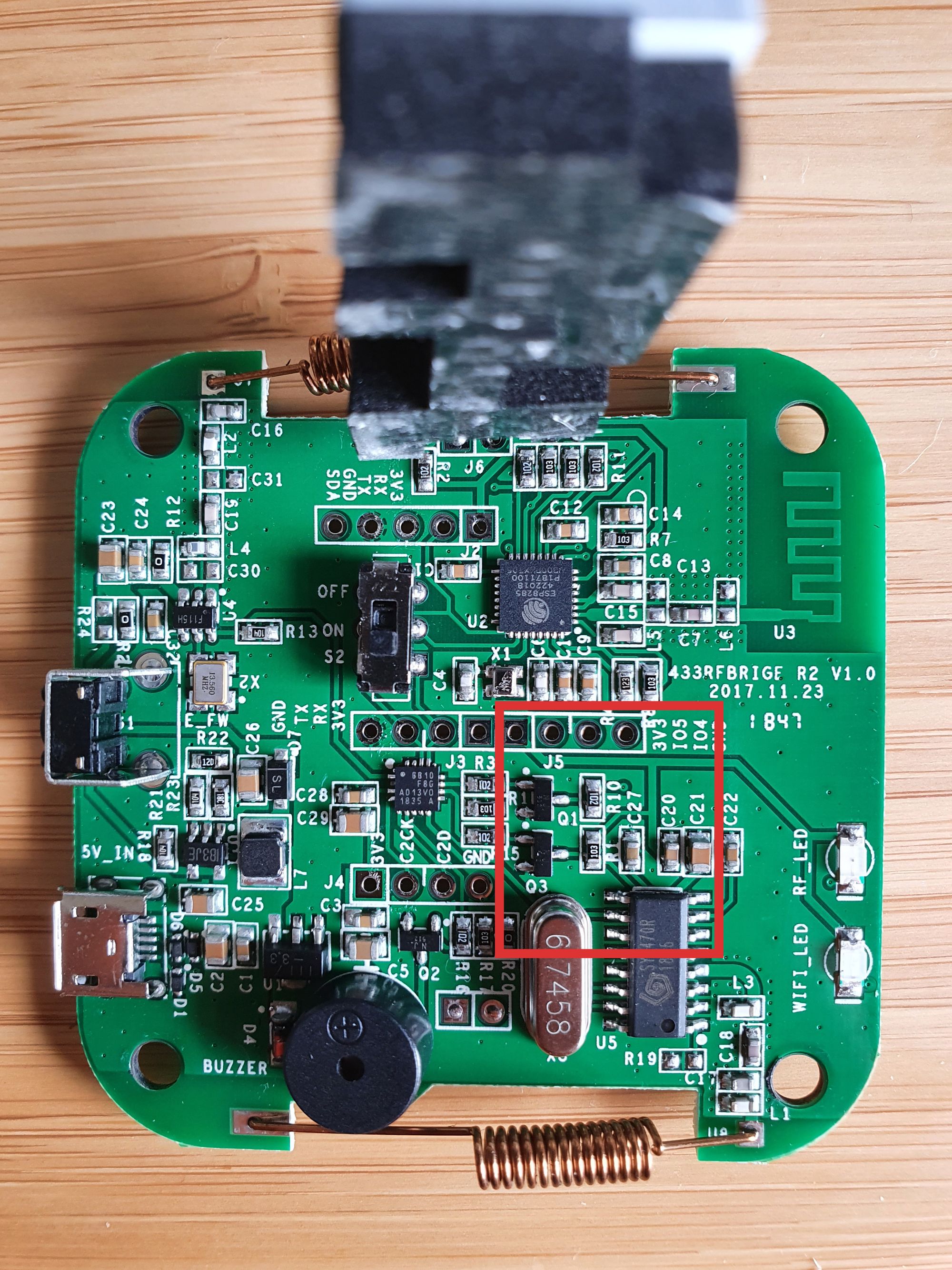
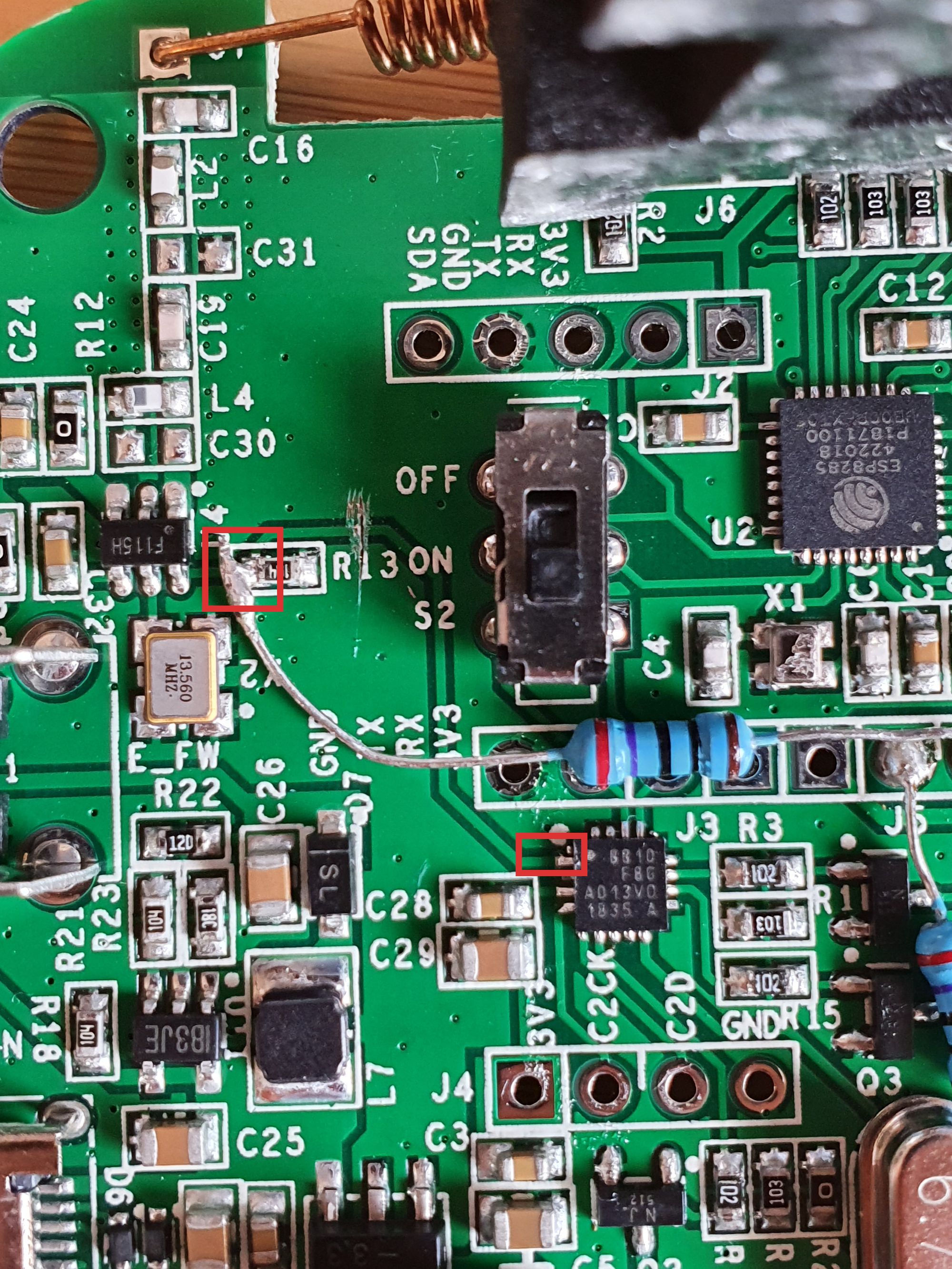
The first step is to identify the area we are working in, with your board in the correct orientation as shown, see the marked area we are working in:
We can then go ahead and solder in a resistor from GPIO4 to pin 10 on the UHF receiver. Remember, on the row of pin headers, GPIO4 is the second pin in from the right on the R1 boards and is the third pin in from the right on R2 boards.
You can see the modification I have made on my R2 board:
Take your time with this, remember less is often more when it comes to soldering. Try not to go overboard with the amount of solder you are using, as you risk bridging the pins next to it.
Modifying the transmitter signal
Modifying the transmitter signal is easier than the receiver signal. It involves connect GPIO5 to R13 on the UHF transmitter.
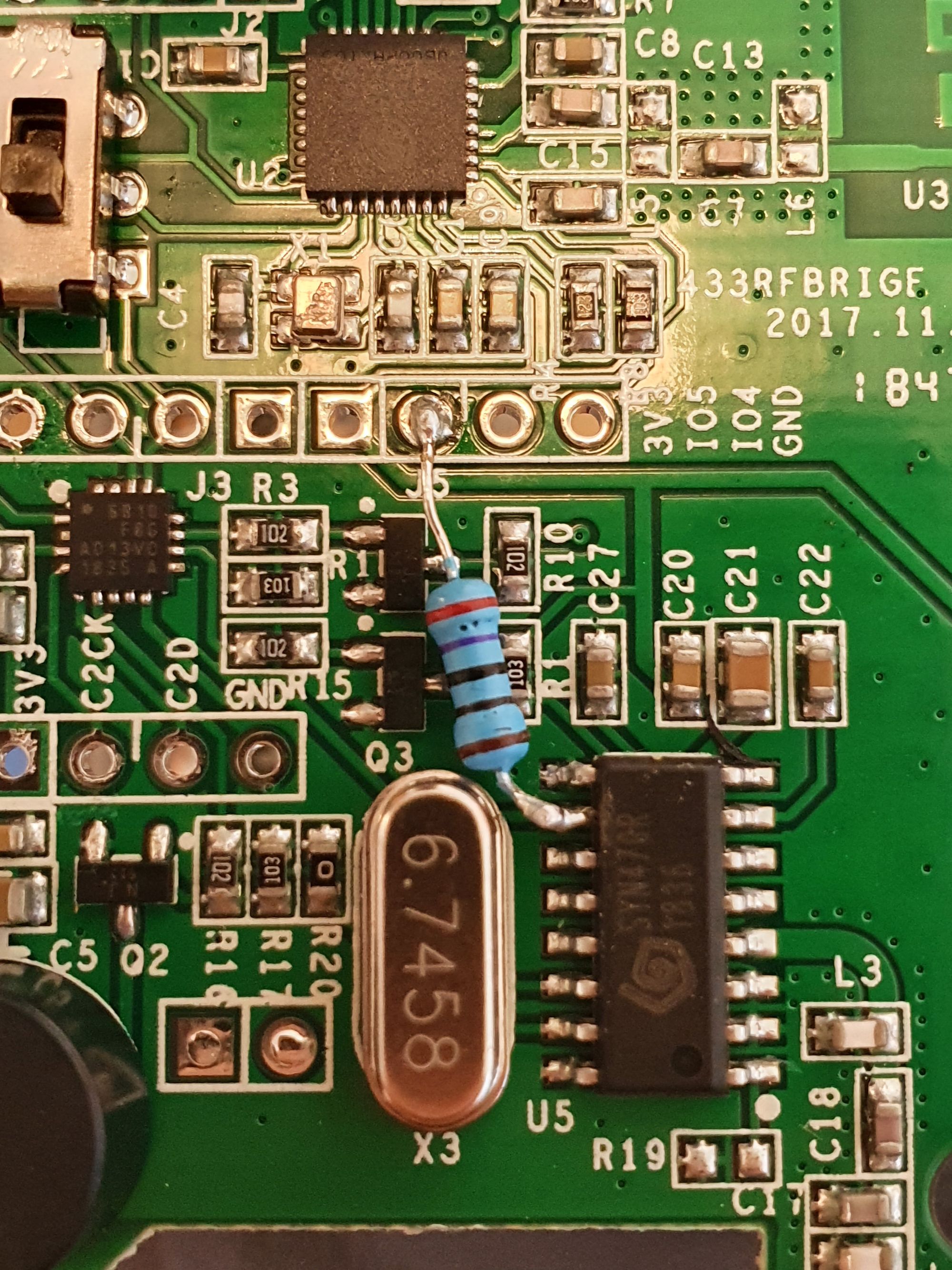
Firstly, identify the area we are working in this time, with your board in the correct orientation as shown, see the marked area we are working in:
Go ahead and solder in a resistor from GPIO5 to R13 on the UHF transmitter. Remember, on the row of pin headers, GPIO5 is the third pin in from the right on the R1 boards and is the second pin in from the right on R2 boards.
You can see the modification I have made on my R2 board:
With that done, the final thing we need to do is cut the trace to the EFM8BB1:
To do this, use a small screwdriver or sharp craft knife. Go slow here and ensure to not damage any of the surrounding traces. You can check if the trace has been cut successfully, you can use a multi-meter in continuity mode to test between these points:
USB line modification
This is an optional but recommended step only for the R2 boards so that you do not get interference from the USB connector when using it for power.
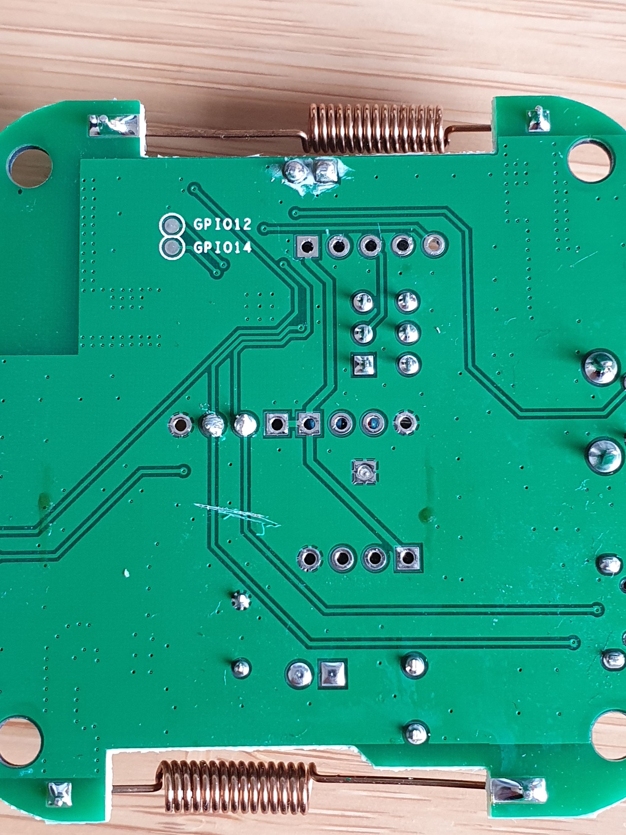
Turn the board over, then identify the area we are working in once again:
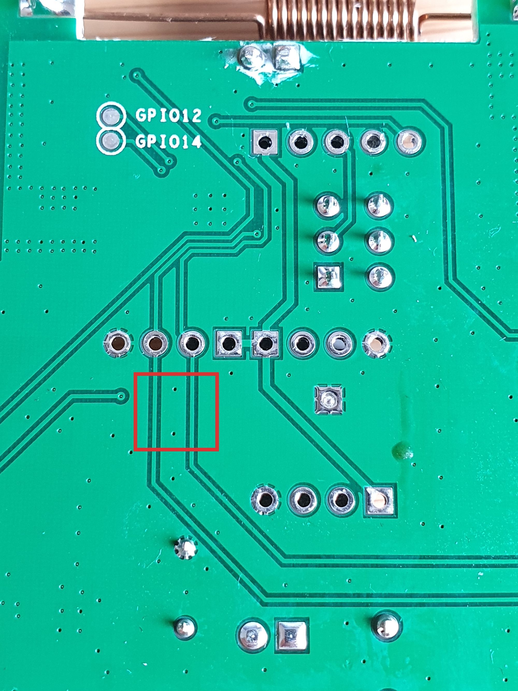
Take a screwdriver or sharp craft knife and cut the traces coming from GPIO4 and GPIO5 to the USB connector:
Unfortunately I couldn’t identify a way to test this with a meter (if someone knows, please let me know) so just take your time with it.
Compiling ESPHome binary for Sonoff RF Bridge
Let’s create an ESPHome firmware for our Sonoff RF Bridge. For our first firmware, the code looks like this:
esphome:
   name: rf_bridge
   platform: ESP8266
   board: esp01_1m

wifi:
   ssid: "wifissid"
   password: "wifipassword"

# Enable logging
logger:

web_server:
  port: 80

# Enable Home Assistant API
api:
  password: "apipassword"

ota:
  password: "otapassword"

remote_receiver:
   pin:
     number: 4
   dump:
   - rc_switch
   filter: 50us
   idle: 2ms
I’m assuming if you are using the Sonoff RF Bridge that you want to capture rc_switch compatible RF codes with ESPHome. If you want you can capture other protocols which you can find here. Be aware if you dump all codes, the logs will probably move very quickly and be difficult to track:
If you already have ESPHome flashed to your Sonoff RF bridge, go ahead and upload it now and skip the next section.
Flashing ESPHome on Sonoff RF Bridge
You should hopefully have the ESPHome firmware.bin file for uploading to your Sonoff RF Bridge (if you are using the ESPHome add-on in Home Assistant, you can download it by clicking compile then download firmware).
I’m assuming you already have your Sonoff RF Bridge flashed with Tasmota or ESPHome. If you don’t, follow this section of the guide.
To upload the ESPHome firmware.bin file using Tasmota, simply go to firmware upgrade from the main menu and upload the file there. Once uploaded, the RF Bridge will reboot and will now have ESPHome on it.
Once flashed, you can then use the ESPHome add-on within Home Assistant to upload config files from here on out.
Sniffing RF Codes
Make sure to add the ESPHome Sonoff RF Bridge to Home Assistant using the integrations menu.
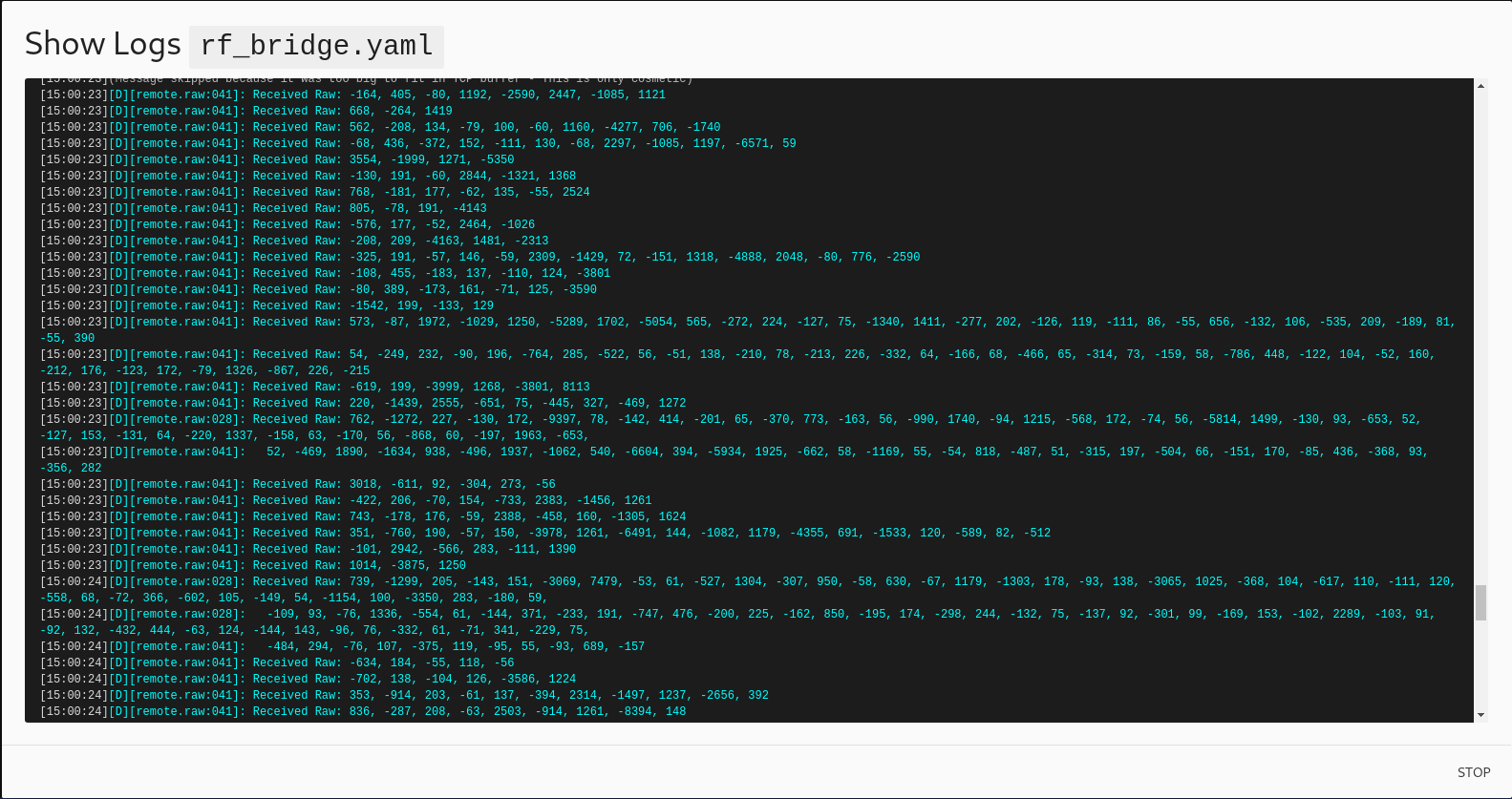
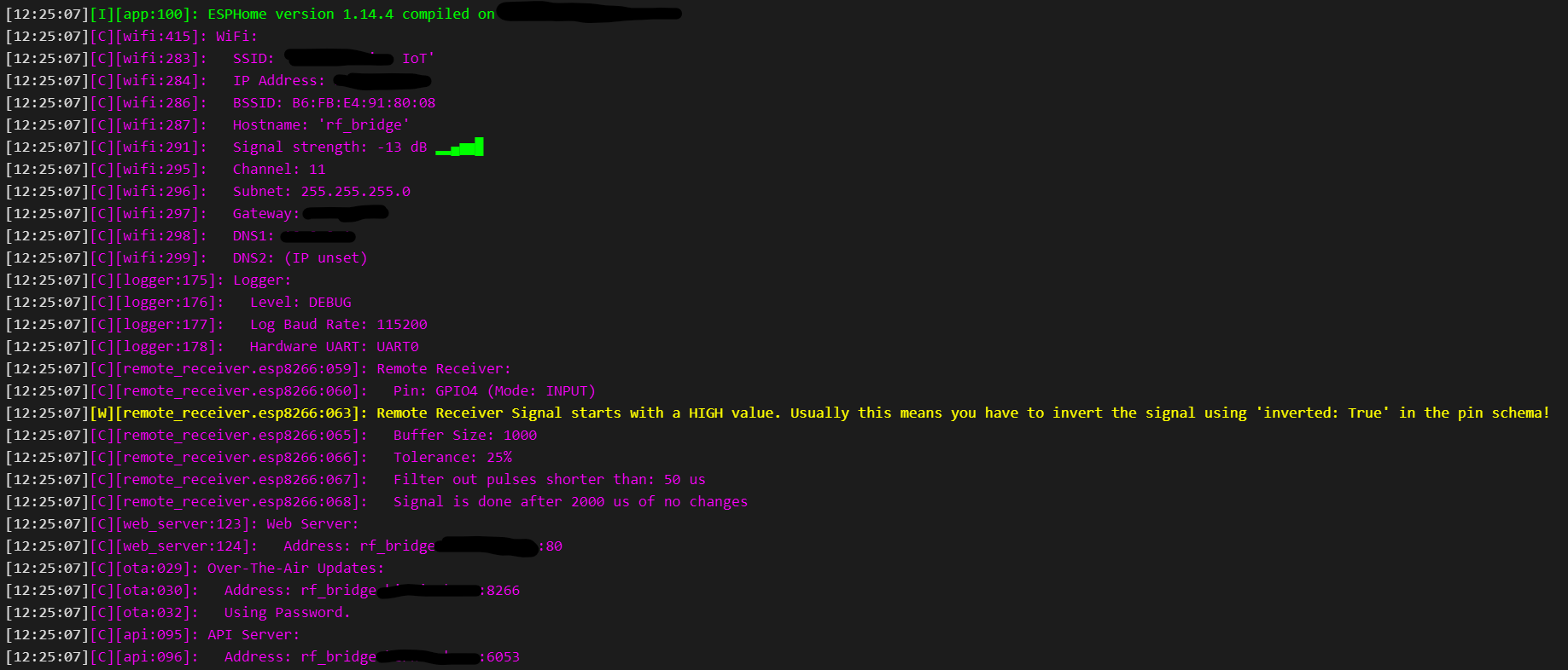
Now that we have ESPHome loaded, we are ready to sniff out RF codes. Using the ESPHome add-on for Home Assistant, open the logs to the bridge (show logs button), you should have something that looks like this:
Now we can start sniffing RF codes. Trigger an RF code for your device by pressing a button, walking in front of a sensor, opening a door or however your devices works and in the logs you will get something like this:
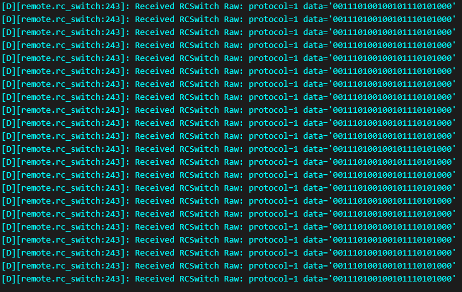
There is two pieces of information we need to take note of, the “data” and the protocol. The data is the unique code that the sensor or device is transmitting, in binary form.
Repeat this process for each device you want to integrate with.
Using this information, we can add sensors to ESPHome.
Adding binary sensors to ESPHome
With the sniffed codes obtained above, we can add them as binary sensors to ESPHome, the following to your existing configuration:
binary_sensor:
   - platform: remote_receiver
     name: "Upstairs Landing Motion"
     device_class: motion
     filters:
      - delayed_off: 10s
     rc_switch_raw:
      code: "0011101001001011"
      protocol: 4

   - platform: remote_receiver
     name: "Living Room Motion"
     device_class: motion
     filters:
      - delayed_off: 10s
     rc_switch_raw:
      code: "010101110110010100101000"
      protocol: 4
Everything should be pretty self explanatory:
- Name – name of the sensor as you want it to appear in Home Assistant.
- device_class – Tells Home Assistant what type of device this is, a list is available here.
- delayed_off – Using the delayed_off filter tells ESPHome to keep this state as on for 10s before setting the device as off. This is useful for motion devices where they only send one signal (motion detected) so without this, ESPHome will immediately set the motion to off making it hard to see in Home Assistant.
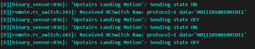
Now when you trigger devices, you will see this in the logs:
Adding devices with multiple codes
You might be wondering how to add devices that have multiple codes, i.e a device that transmits different codes for on and and off, like a door sensor.
I wish ESPHome had native support right within the platform for this but we can achieve what we want with templates:
  - platform: template
     name: "Front Door"
     device_class: door
     id: switchfrontdoor

  - platform: remote_receiver
     name: "Front Door Open"
     internal: true
     on_press:
       then:
         - binary_sensor.template.publish:
             id: switchfrontdoor
             state: ON
     rc_switch_raw:
       code: '001001011000100010101110'
       protocol: 1

   - platform: remote_receiver
     name: "Front Door Close"
     internal: true
     on_press:
       then:
         - binary_sensor.template.publish:
             id: switchfrontdoor
             state: OFF
     rc_switch_raw:
       code: '001001011000100010100111'
       protocol: 1
The first block is our binary sensor template, with the device_class set to door, and a unique id that we will reference.
Our second block is an internal (is not exposed to Home Assistant) sensor that when it receives the open code, will publish the “ON” state to the Front Door binary sensor using the unique ID.
The third block does the same as the second but uses the closed code and OFF state.
Transmitting Codes
You can also transmit RF codes from the RF bridge using the remote_transmitter platform. Using a switch we can transmit any code we want:
remote_transmitter:
  pin: GPIO5
  carrier_duty_percent: 50%

switch:
  - platform: template
    name: "Siren"
    turn_on_action:
      remote_transmitter.transmit_rc_switch_raw:
      code: '00110111011010000101'
      protocol: 1
Conclusion
You should now be able to fully integrate ESPHome with your Sonoff RF Bridge and use it to receive and transmit RF codes on the 433MHz frequency.
If you have any issues, let me know in the comments and be sure to subscribe below for instant updates of new topics.