How to make your own dual-purpose wireless alarm system with Home Assistant - Part 1

Ever looked at adding an alarm system to your house only to overwhelmed by the plethora of options out there? We get you, it can be very hard to make a choice because once you do, you are often locked into that providers ecosystem with very limited compatibility with other devices, not to mention the price that a lot of these systems command.
With that in mind, we set out to create our own “alarm system” that wouldn’t break the bank. I’ve been using this exact (almost!) setup for a year now and I have to say, it has been flawless. So much so that I was was actually surprised at how good it has been. And for those who don’t want to/can’t make modifications to their property, being wireless is a nice bonus!
Using Home Assistant as our central hub for our wireless alarm, I’ll show you how to add multiple different types of sensors, create automations, send notifications and even a bonus function!
Table of Contents
- Disclaimer
- The Aim
- Prerequisites
- Guide
- Introduction
- Parts List
- Flashing Sonoff RF Bridge
- Sniffing devices
- Home Assistant
- Adding an Alarm Panel
- Final Words
Disclaimer
It goes without saying that this is not designed to be a professional alarm system by any means, please do not use this as your sole method of protecting anything. Since we are using RF transmission, there are methods of blocking the transmission which could be used to bypass this. You should always have more than one alarm system for serious protection.
This was put together as a fun project which does function well for the average household and comes with a few other benefits outside of security. Obviously this will be better than not having an alarm system in the first place, but please do not rely on this.
The aim
There was a couple of goals we had in mind when we sat down to plan this, all of which we wanted to meet:
- As cost efficient as possible
- 100% wireless with decent battery life
- Easily expandable
- Home Assistant integration
- Bonus feature – motion sensors to double as room presence for lighting
Cost – I think we did extremely well here (if we do say so ourselves!) as you will see, many dumb alarm systems can run into the £1000s, we are coming in at less than £100 for our setup.
Wireless – another headache with traditional systems is the need to hardwire everything (understandably of course) but running wires all around your house isn’t always ideal for everyone, so making the whole system wireless was essential so that everyone can get involved with this project!
Expandability – we wanted you to be able to test this out with just a few devices at first and if you like it then being able to easily add new devices was a must have.
Home Assistant integration – with all of our devices in Home Assistant, this was a no brainer.
Bonus feature – when we think of traditional systems, we see the motion sensors that have a single function, to detect any motion within the area, but we thought if we are putting these things all over our house, why not utilize them for turning on our smart lights? Of course, the home assistant integration by default helps us to tackle this issues.
Prerequisites
- Esptool installed on a laptop and you know how to flash Sonoff devices (no solder required for this one!)
- A working home assistant installation, see our getting started with home assistant series here if you do not have this.
- An MQTT broker
- Knowledge of how to add sensors to home assistant via config files, see part 4 of the getting started with home assistant series here.
Guide
Introduction
So, how does it work?
When setting out to our first 3 goals above, we needed to find a good method of transmission whilst remaining affordable. The natural choice for this is RF transmission because of its low power requirements, popularity and general simpleness.
A quick search on Amazon confirms a plethora of cheap RF sensors, many of which are designed to work with that providers own alarm, question is, could we hack them to work with our own and integrate with Home Assistant?
I ordered one RF motion sensors and hooked up a 433mhz receiver to a Raspberry Pi, hacked some code together (really hacked together!!) and initial tests confirmed that yes you can use any generic sensor.
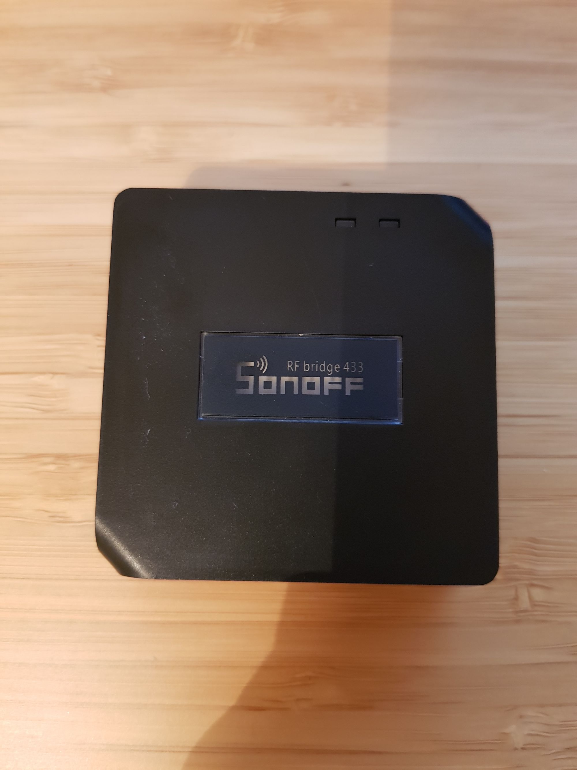
Great, so we have the protocol but how to make it easy for everyone to use? The Sonoff RF bridge of course! This Sonoff module is capable of both sending and receiving 433mhz transmissions from our alarm sensors without any real effort. This solves goals 4 and 5 since we know we can install Tasmota and get Home Assistant integration.
Tl;dr 433mhz alarm sensors communicating with Sonoff RF Bridge, which in turn speaks to home assistant via MQTT.
Part List
There are a few parts for this section of the guide that we will need:
- Sonoff RF Bridge
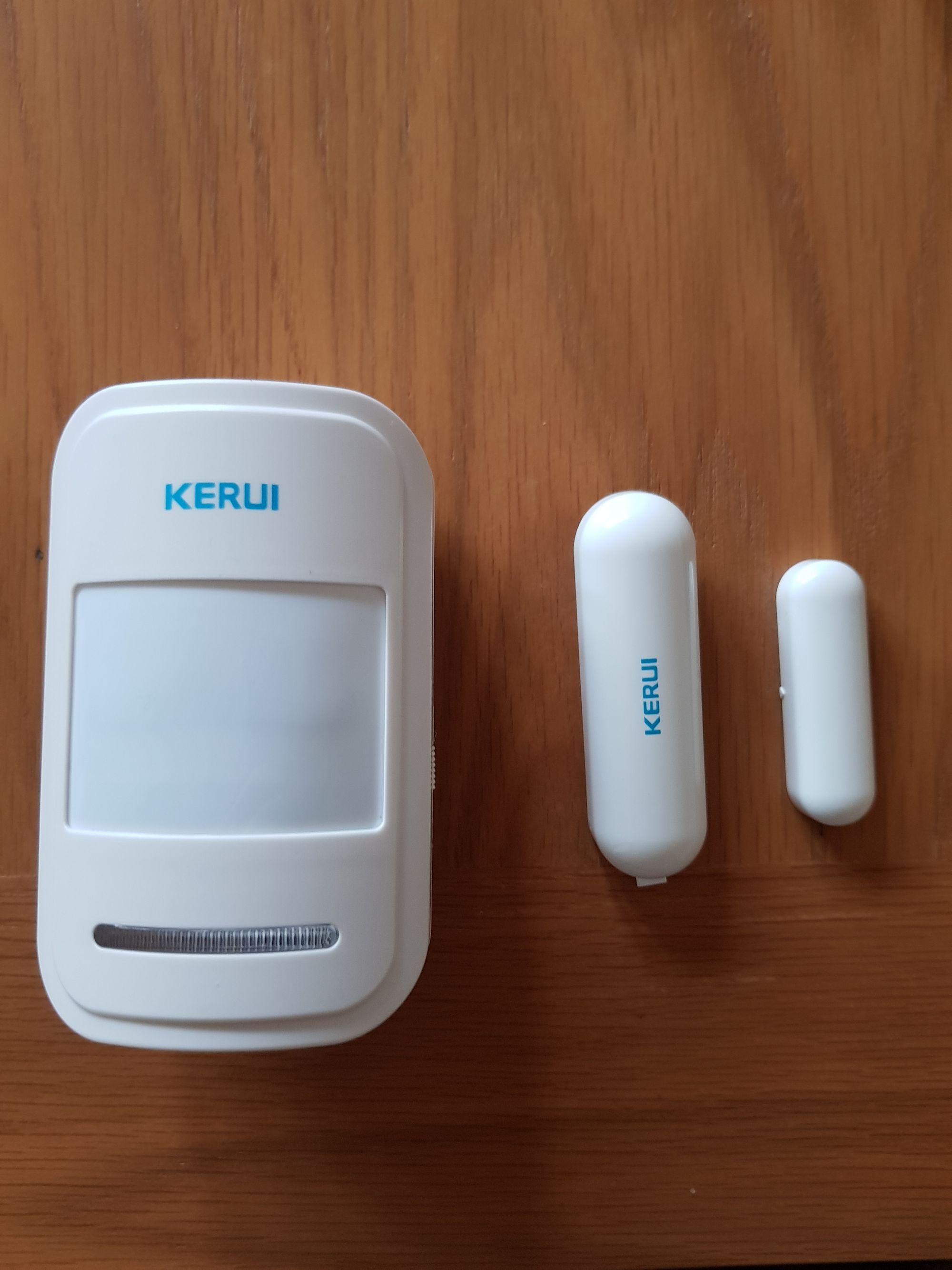
- 433mhz PIR/Motion Sensor – I’m using one from KERUI but I have tested others which work fine. Just make sure it is 433mhz
- 433mhz Door Sensor – Again using the KERUI ones, get these if you can, they make a really slim and discreet one!
- FTDI USB to Serial adapter
- Male to female jumpers – for flashing Sonoff (don’t worry, no solder!)
Flashing Sonoff RF Bridge
The first thing we are going to do is to get the Sonoff Bridge flashed with Tasmota, since it makes setup pretty easy for us.
Go ahead and download Tasmota Basic from here. I am using a slightly older version but just download the latest release. Note Sonoff-Tasmota has been renamed to just Tasmota as of version 7.0.
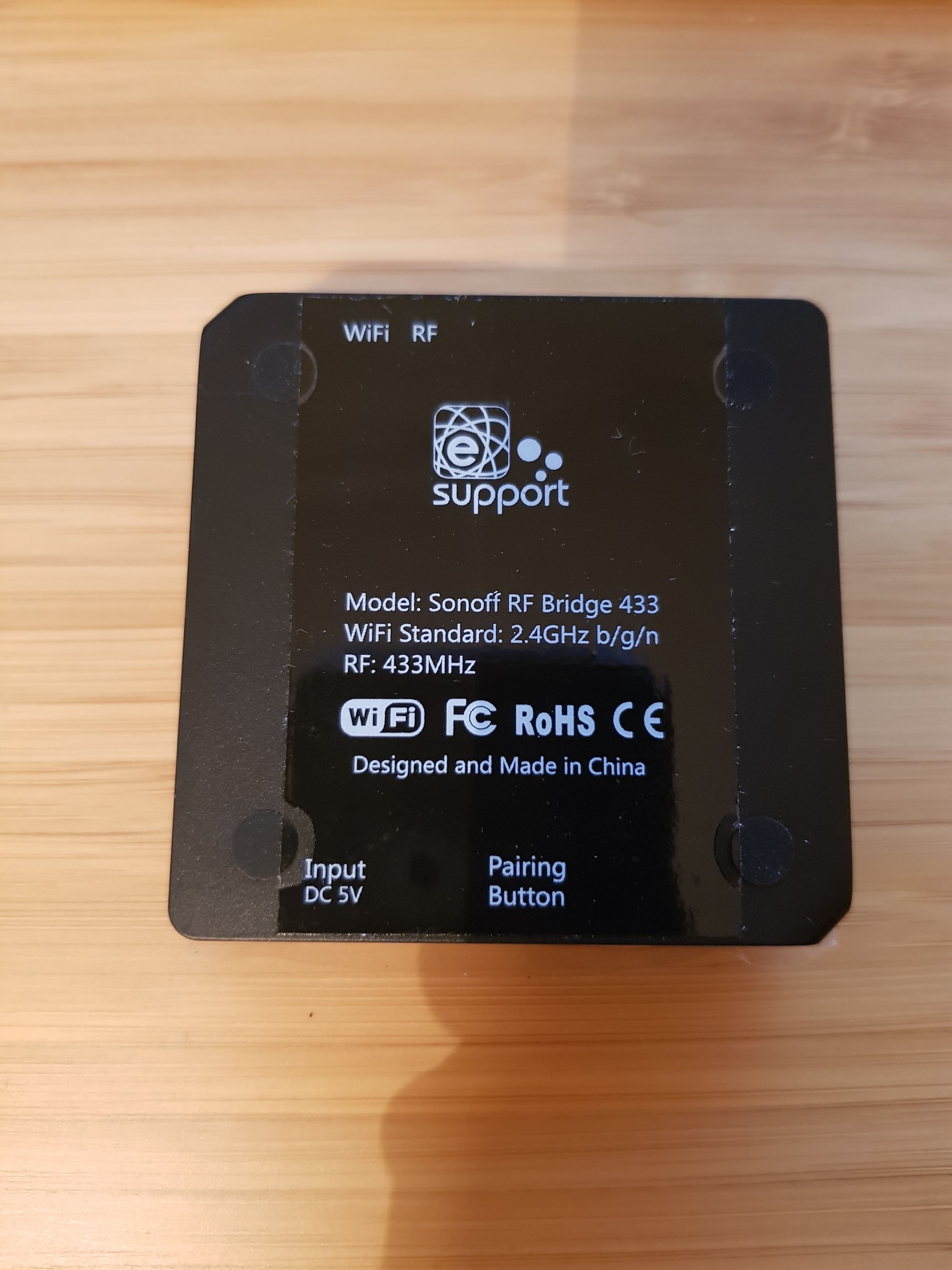
We need to open the Sonoff RF Bridge to gain access to the pins to flash it with Tasmota. Go ahead and remove the 4 rubber feet and remove the 4 screws underneath, then simply pull the case apart and remove the PCB from the casing:
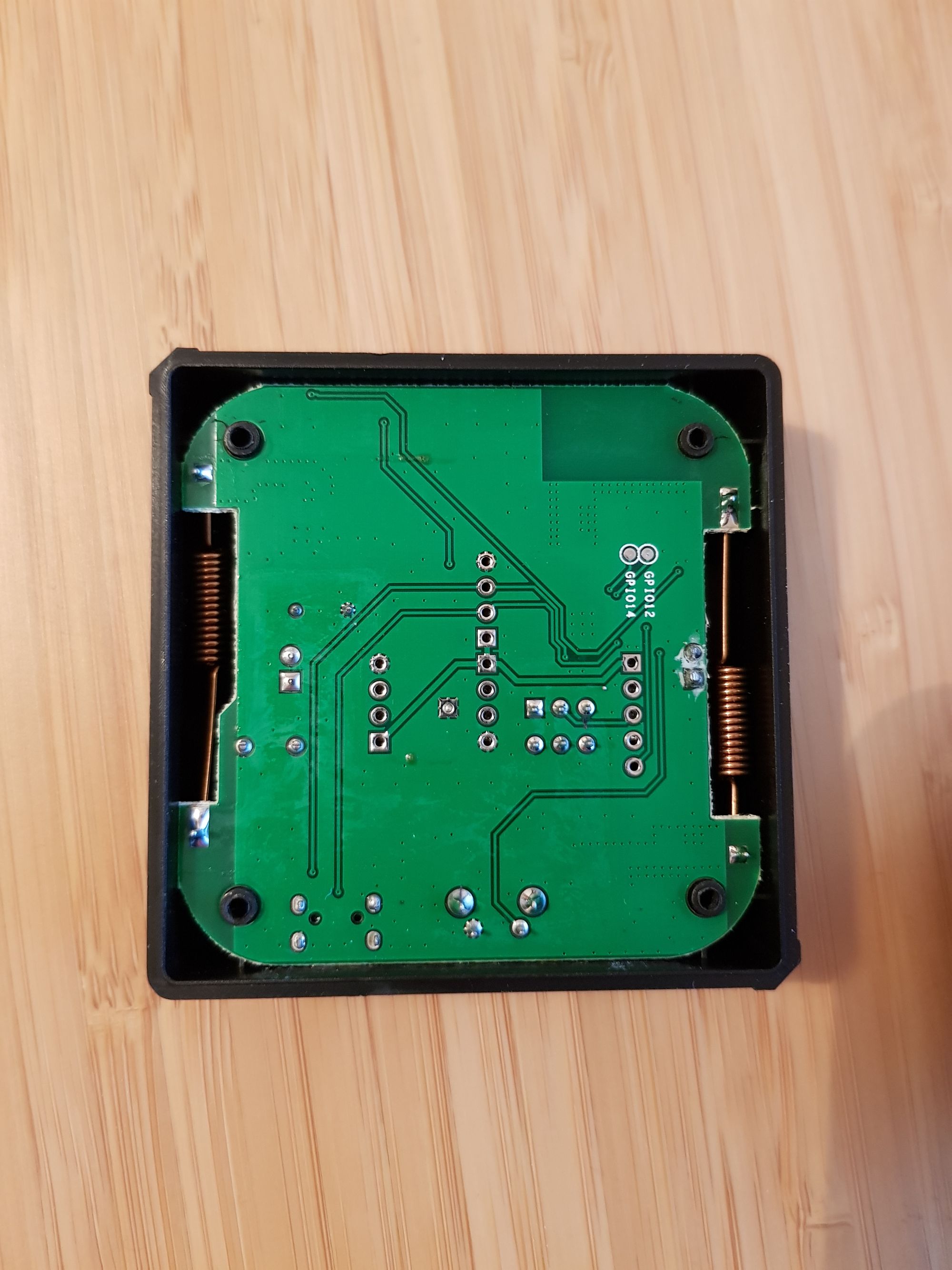
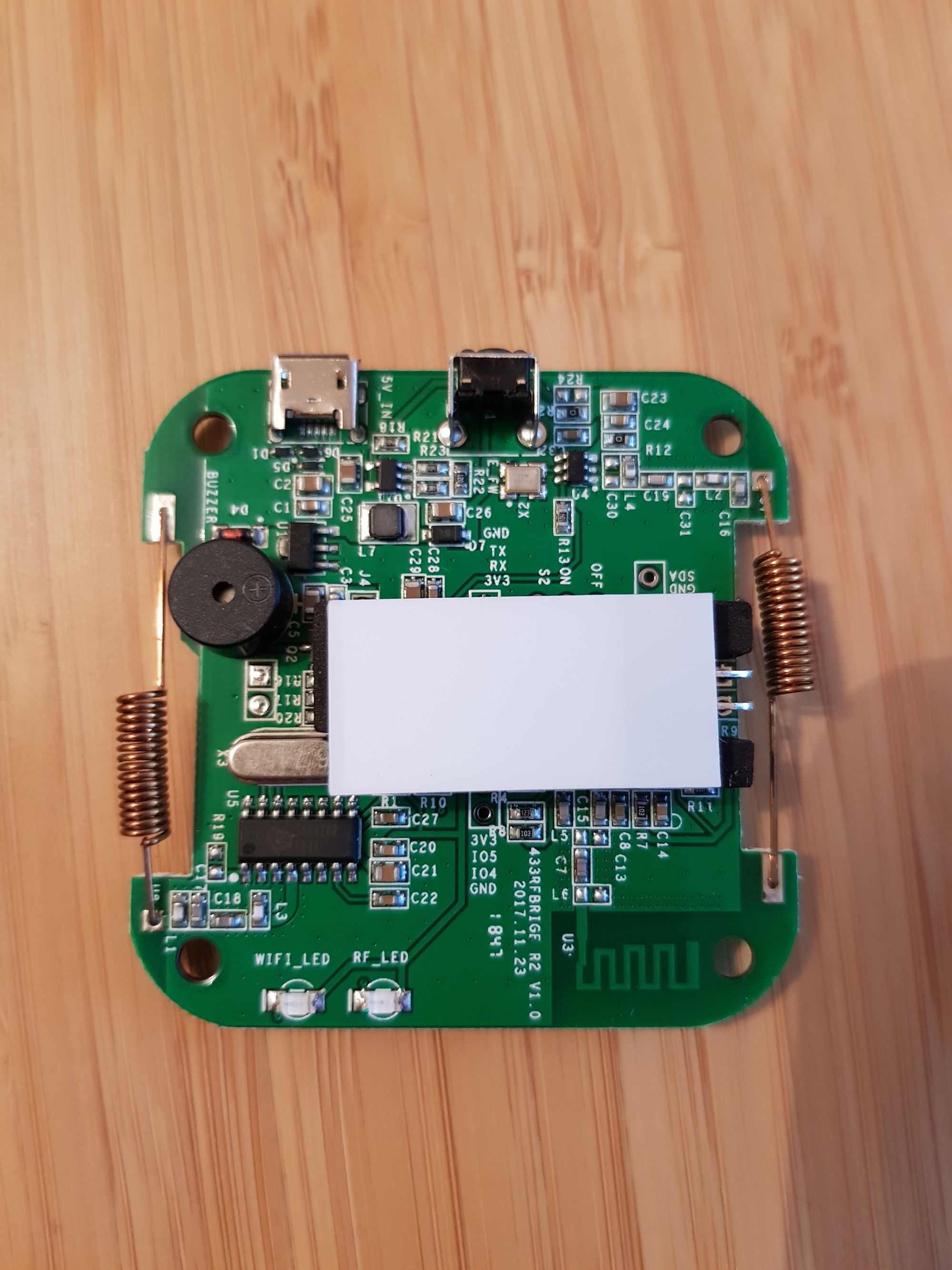
It’s worth noting that there are a few different versions of this board from what I can tell, but all are the same. Some have the LED screen on them and some don’t (the big white rectangle in image 5). If you have the LED screen, go ahead and gently bend it upwards, that will give us access to the pins we need below.
Next connect the female end of the jumper cables to your FTDI serial adapter, you will need 3.3v, Ground, RX and TX connected. Make sure the voltage is set to 3.3v and NOT 5v. Make sure the FTDI is disconnected from the USB port of your laptop for now.
Next find the 4 pins we need on the board (I am using a different image for this, so the board looks a little different), they are identified by the red rectangle number 1:
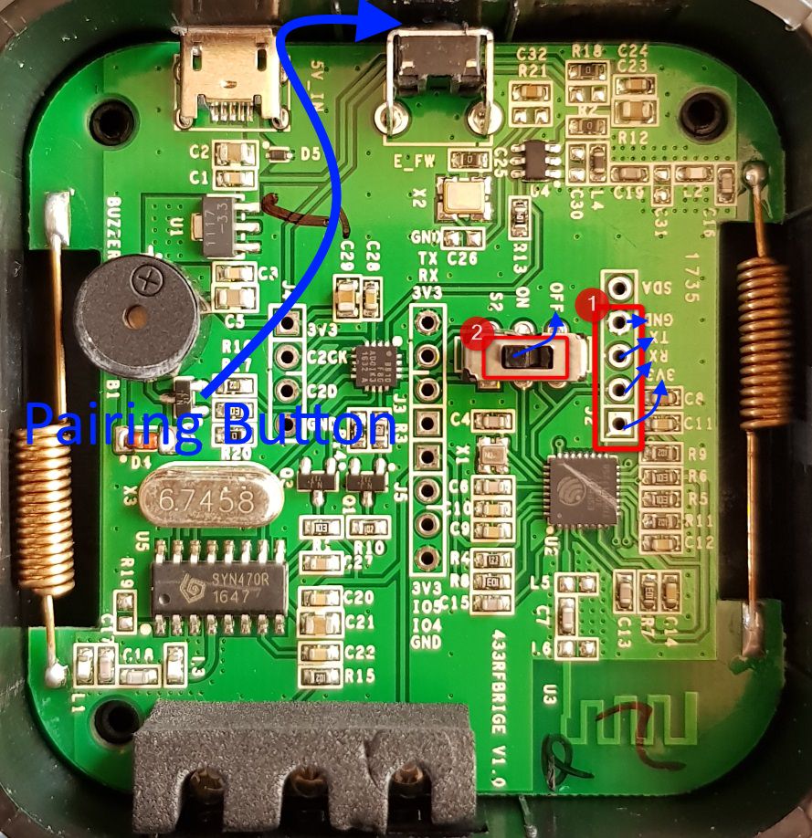
Connect the male end of the jumper cables, to their corresponding pins:
| Sonoff RF Bridge | FTDI USB to Serial |
|---|---|
| 3.3v | 3.3v |
| Ground | Ground |
| RX | TX |
| TX | RX |
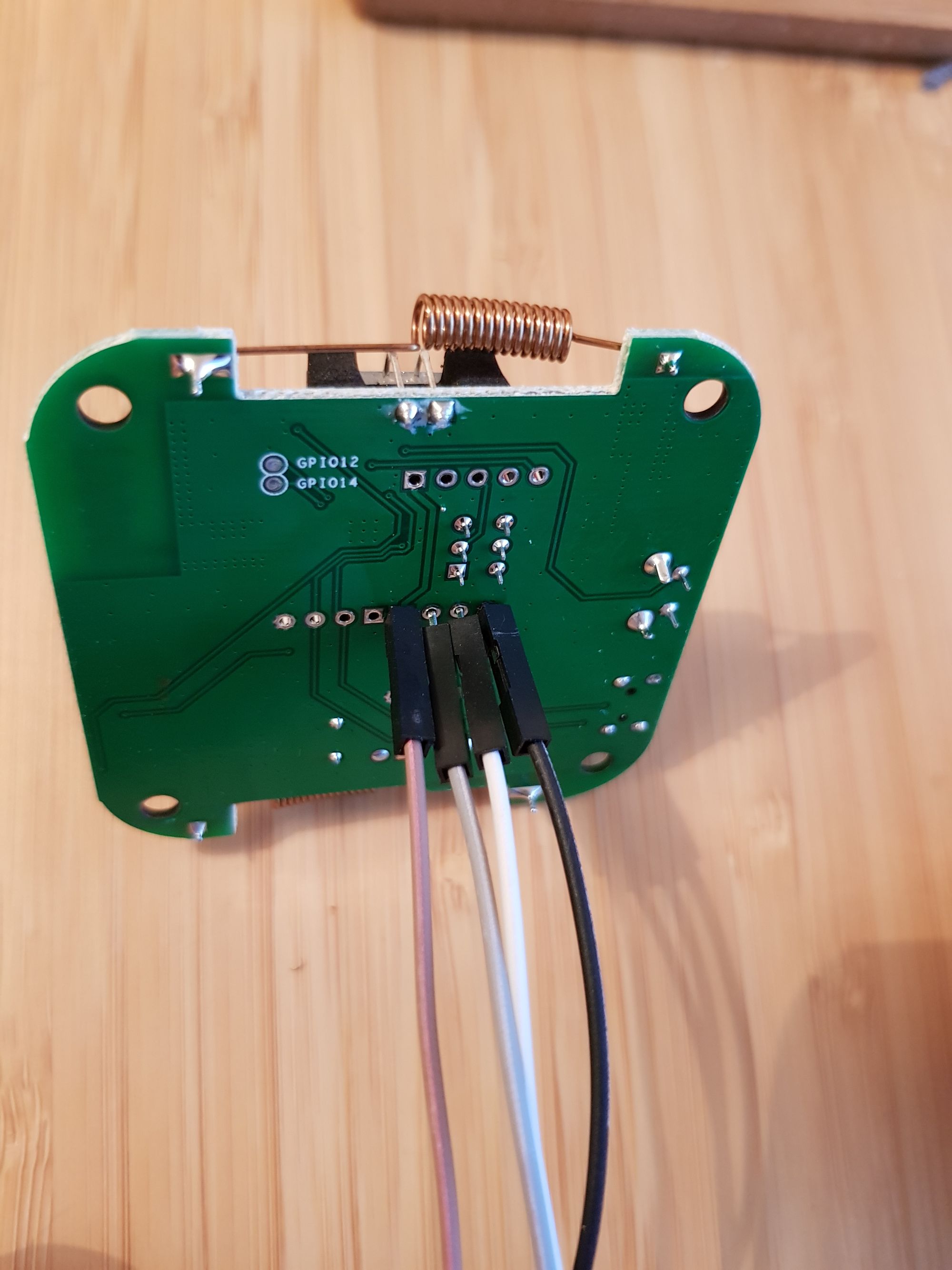
Note that they just sit loosely in the hole, you may need to apply just a slight amount of pressure to ensure contact, this is fine:
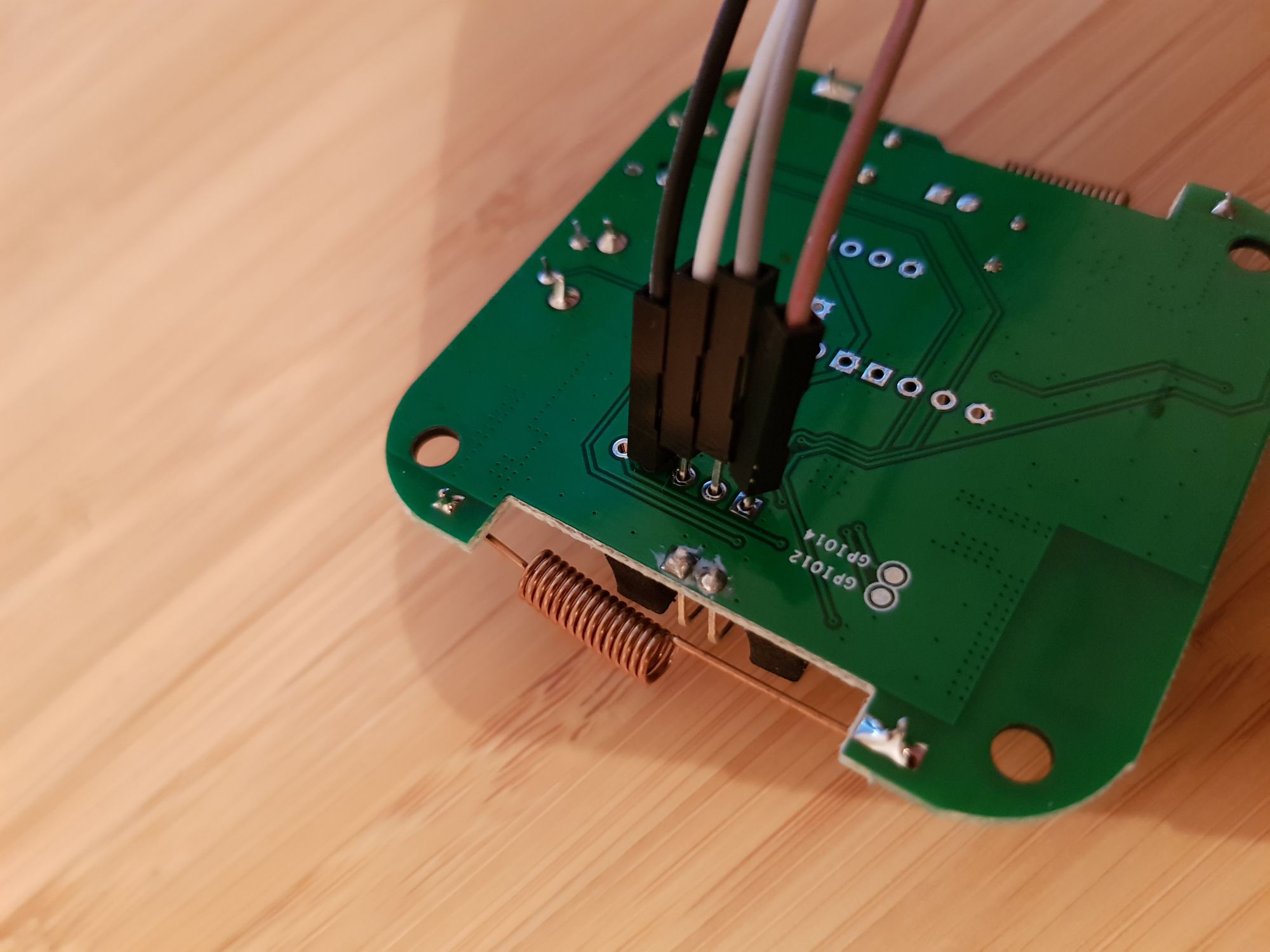
Next, ensure the switch (identified as number 2 in the above image) is set to the off position.
Finally, hold down the pairing button whilst plugging the USB to Serial adapter into your laptop. After 2 seconds, you may release the pairing button.
So to summarize:
- Connect jumper pins on USB adapter, ensure 3.3v is set
- Connect other ends of jumper cables to Sonoff Bridge
- Ensure switch on Sonoff is in the off position
- Hold pairing button and connect USB adapter to laptop
The Sonoff RF bridge is now in pairing mode, we can now flash Tasmota using esptool and the following commands:
1. Backup original
Windows:
esptool --port YOUR_COM_PORT --baud 115200 read_flash 0x00000 0x100000 sonoff-bridge-original.bin

Linux:
esptool --port /dev/YOUR_COM_PORT --baud 115200 read_flash 0x00000 0x100000 sonoff-bridge-original.bin

2. Erase Flash
Windows:
esptool --port YOUR_COM_PORT erase_flash

Linux:
esptool --port /dev/YOUR_COM_PORT erase_flash

3. Flash Tasmota
Windows:
esptool --port YOUR_COM_PORT write_flash -fs 1MB -fm dout 0x0 tasmota.bin

Linux:
esptool --port /dev/YOUR_COM_PORT write_flash -fs 1MB -fm dout 0x0 tasmota.bin
You can then remove the jumper cables and re-assemble, remember to put the switch back to the on position.
Once complete, using your laptop or phone, scan for wifi networks and you should see a Sonoff wifi network i.e sonoff-XXX, connect to this and go to IP address 192.168.4.1, you can then complete the setup process by joining the bridge to your wifi network:
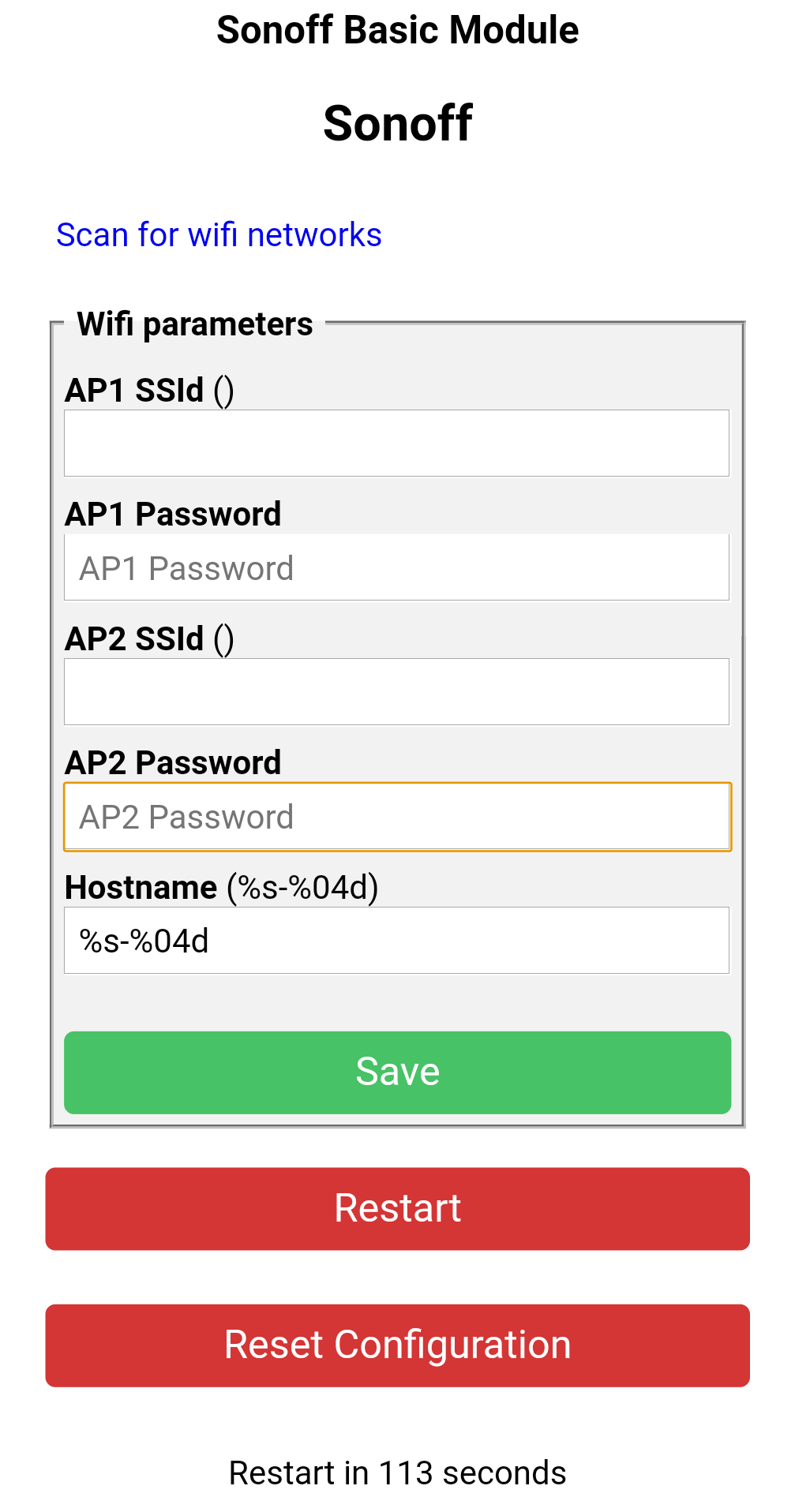
Hit save, then reconnect to your wifi, then connect to the bridge again on its new IP address (you will need to find this out).
Once connected to the device again, you will be on the home page (again your page might look slightly different depending on the version):
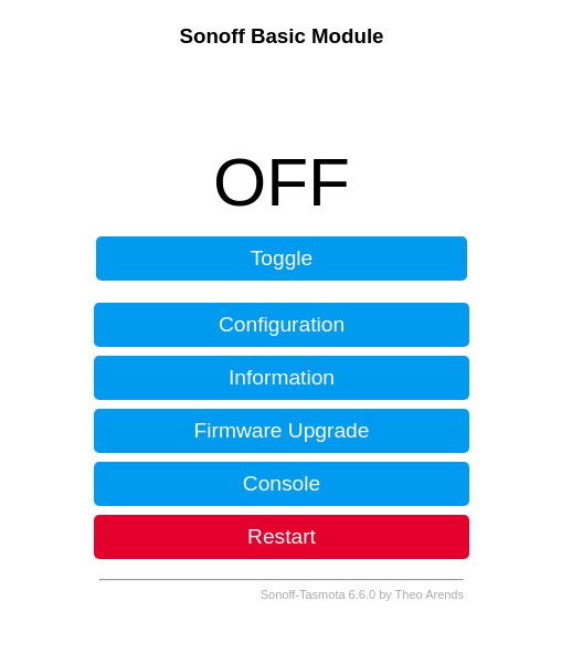
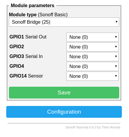
Navigate to configuration, configure module and set the module to “Sonoff Bridge (25)” and press save:
The module will restart and after a few seconds. We will then do the following 3 things, all under the configuration menu:
- Under Wifi, set a hostname
- Under Other, set a friendly name
- Under MQTT, configure your MQTT broker settings, as well as the topic format you want to use.
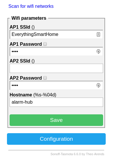
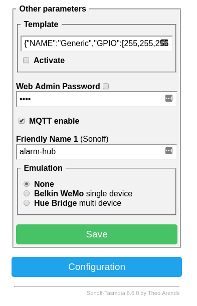
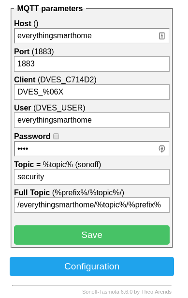
That’s all we need to with the RF Bridge..for now!
Sniffing devices
Next we need to sniff the unique codes that are transmitted from our devices.
When the state of our sensors change, i.e motion detected or door opened/closed, our device will broadcast a unique code that we need to “learn” – each device has its own code and can only be figured out by listening.
Power on the devices by inserting the batteries and removing the tab. Here you can see I have a motion sensor and door sensor:
The door sensors are really simple to setup, the motion sensors have a couple of options you can tweak such as sensitivity level and battery saving mode which disables the light inside to save power, you do this by setting a couple of jumpers or switches on the inside:
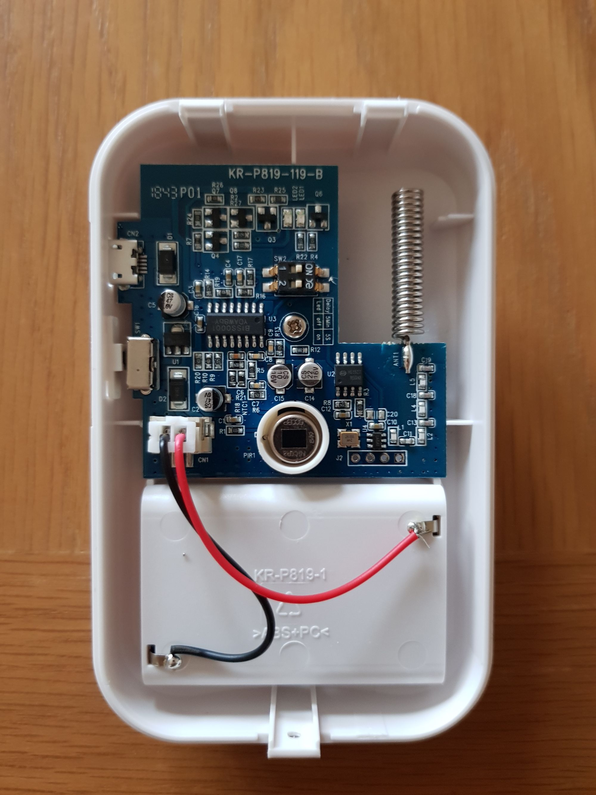
Notice the Switch 1 and Switch 2 in the middle-upper portion of the picture.
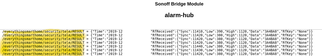
So with the devices powered on, we need to go back into the RF bridge web page, and open the console. Next trigger each of the devices in turn (do one at a time) and you will see some entries appear in the console, this produces a JSON result that has the unique code, within the “RfRecieved.Data” object:
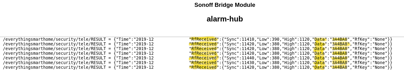
The payload in the above example is 3A4BA8.
Take a note of the entire line into a notepad and write yourself a little note to remind yourself which device it is.
Repeat this for each sensor you have. Note that motion sensors only have one code – when motion is detected. Door sensors have two codes, an open code and a close code. So make sure to note both of these!
For a single motion sensor and single door sensor, you will have 3 codes.
With all your codes learned, lets move onto adding these as sensors to Home Assistant which will help trigger our alarm.
Home Assistant
Jumping into Home Assistant, we are going to add each of these alarm sensors as a binary sensor, since they have only 2 states i.e motion or no motion, door open or closed.
Jumping into the config file (see part 3 of the Getting Started with Home Assistant Series for how to add sensors), I’m assuming you already have the MQTT broker up running. Let’s go ahead and add the motion sensor as a binary sensor:
binary_sensor:
  - platform: mqtt
    name: "Hall Motion"
    state_topic: "/everythingsmarthome/security/tele/RESULT"
    value_template: '{{ value_json.RfReceived.Data}}'
    payload_on: "3A4BA8"
    payload_off: "off"
    device_class: Motion
    qos: 1
    off_delay: "10"
So lets break this down, the first line tells Home Assistant we are declaring a binary sensor, second line says that the platform we are using is MQTT based. Third line is the name we are giving to the sensor, these should be unique and are what is shown in Home Assistant. Next, we tell Home Assistant where the MQTT Topic to monitor for data is. You can get this from the console line from earlier:
The value_template is where the magic happens, without this there is no way to distinguish between devices. So that value_template tells home assistant to extract the value from the JSON string, in this case we are telling it to extract the value from “RfReceived.Data” object.
The on payload is the codes we noted down earlier, in this example I’m using 3A4BA8 as my motion detect code. The off payload is just “off”, in truth it can be anything you want, since there is no “off” for motion. This isn’t true of the door sensor as you will see.
The device class tweaks a few variables in Home Assistant to tailor to your device, you can view them here.
QOS is just the MQTT Quality of Service value to ensure delivery.
The off_delay value is what sets the sensor back to off if it does not receive a motion event for 10 seconds.
Adding the door sensor would look like this:
  - platform: mqtt
    name: "Front Door Sensor"
    state_topic: "/everythingsmarthome/security/tele/RESULT"
    value_template: '{{ value_json.RfReceived.Data}}'
    payload_on: 'ABCDEF'
    payload_off: 'FEDCBA'
    device_class: door
    qos: 1
Very similar, the only difference is we have an actual off payload, since the door sensor has an opened and closed state.
Restart Home Assistant to pick up the new sensors:

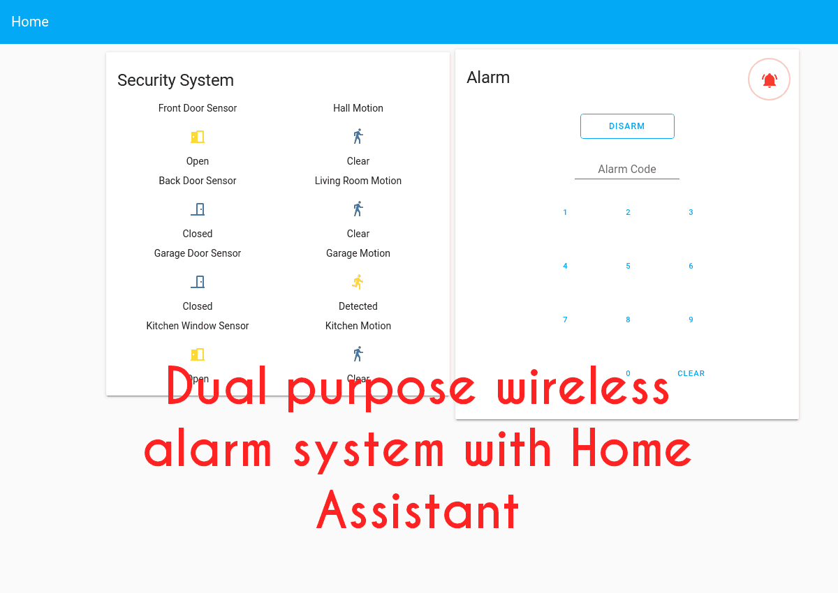
I’ve added these two sensors to a glance card where you can see them in the normal and triggered state, give it a try and trigger your sensors:
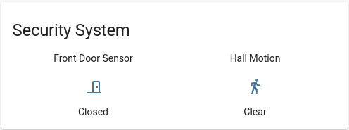
Trigger the sensors a couple of times to make sure everything is working OK.
You can go ahead and repeat these steps for any additional sensors you might have!
Adding an alarm panel
Now that we have 2 working sensors, let’s add an alarm panel to Home Assistant. The alarm panel allows you to arm and disarm the house from within Home Assistant.
Make a quick change to the configuration file like so:
alarm_control_panel:
  - platform: manual
    name: Home Alarm
    code: 123456
    pending_time: 30
    delay_time: 20
    trigger_time: 120
    disarmed:
      trigger_time: 0
    armed_home:
      pending_time: 1
      delay_time: 1
      trigger_time: 120
Make sure to set the options to how you want them for your environment. You can view an explanation of all the options here.
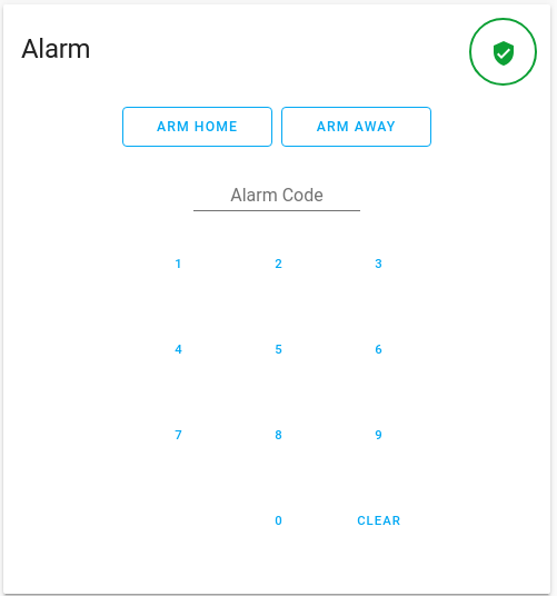
Restart Home Assistant. Then in lovelace, we need to add an alarm panel:
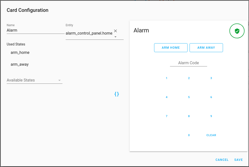
After this, you can go ahead and test it out by typing in the code and arming the system:
Great so we can set the alarm but the elephant in the room is…how do we trigger it!?
Good question, lets set that up now. Head into Configuration, Automations and add a new automation. We will call this Alarm – Away Mode – Triggers. We are going to add our sensors as triggers:
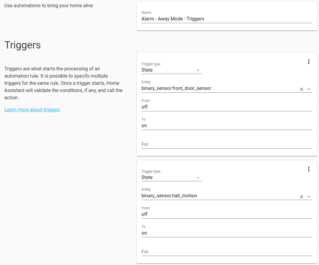
Note that the state is off to on as opposed to closed to open, these are binary sensors remember.
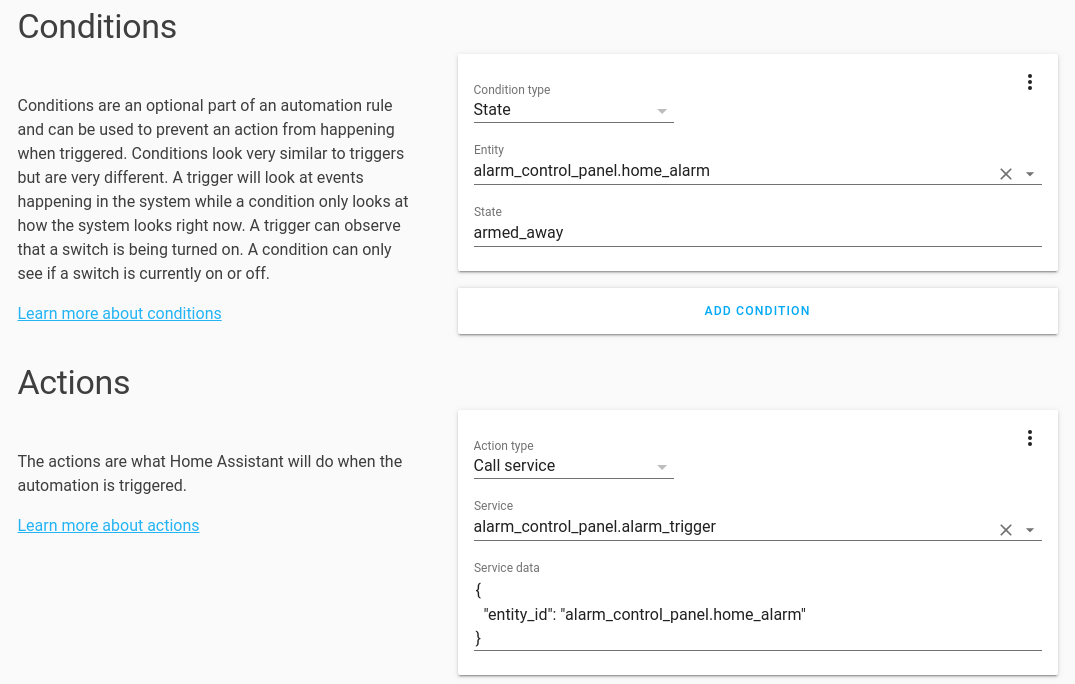
Next we add the condition that the alarm panel must be in the away state since we don’t want the alarm triggering as move around the house normally. We also set the action to trigger the alarm:
Save the new automation.
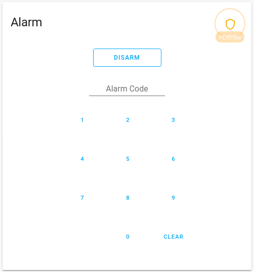
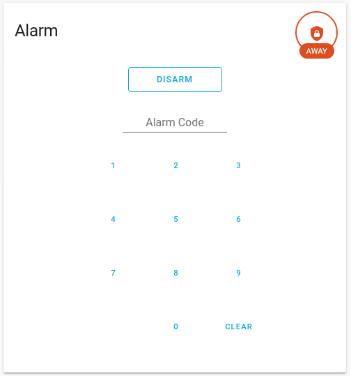
Let’s give it a test by arming the alarm, then triggering one of the sensors, the alarm should move to the pending state (which gives you time to disable it) then it will move to the triggered state:

Everything seems to be working great! Of course if you have multiple sensors you can add them into the automation.
Final Words
We should now hopefully have a fully functioning wireless alarm system working with Home Assistant! From here there are many things we can do by expanding this, the major one being that we want notifications of the alarm being triggered, this will be covered in part 2, along with the motion lights which are easy and some other functions.
As always, feel free to leave your comments below and let me know if you managed to build this! Stay tuned for part 2 which will drop soon.
Merry Christmas and a Happy New Year to you all!