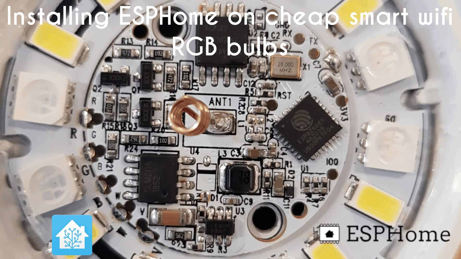
How to install ESPHome or Tasmota on a cheap smart wifi RGB bulb

Recently I started looking at alternative ways to achieve Philips Hue lighting, without spending the money that Philips Hue commands. Don’t get me wrong, Philips Hue is a great product and works very well, just that it is a very expensive ecosystem to join.
After a little digging, I found that there are literally thousands of bulbs on Amazon. So where to start?
Luckily, the vast majority of these bulbs come from a single vendor, Tuya, and are then rebranded. This means that they are all pretty much identical under the hood.
Inside of these bulbs is the ever popular esp8266, which, as you guessed, means we can modify it to suit our needs. I’m going to show you how to install ESPHome on your smart bulb here, but the process should be the same for Tasmota or other variations.
Let’s get into it!
Tuya-Convert vs ESPTool/Soldering
Right off the bat, there are 2 ways to install ESPHome or Tasmota on your smart bulb.
The first method is tuya-convert which provides a “solderless” and much easier method of flashing these and can be done with a laptop and a smart phone. This is by far the easier method. Unfortunately Tuya started rolling out patches for this sometime at the start of the year which prevents tuya-convert from working. Some bulbs are on this new firmware out of the box, some are not. My recommendation is to try tuya-convert first – and whatever you do, do not connect your light to the Smart Life app, this will automatically flash the bulb and Tuya-Convert will no longer be an option.
I’d definitely recommend trying Tuya-Convert first, please see my other guide here.
Parts list:
- A smart wifi bulb (make sure it uses the “Smart Life” app)
- USB to Serial FTDI adapter
- USB to mini usb cable
This guide assumes you have experience soldering and have access to soldering equipment. If you do not, please try the tuya-convert method mentioned above. If I can obtain a compatible device, I will write a guide using that method in the future.
Guide:
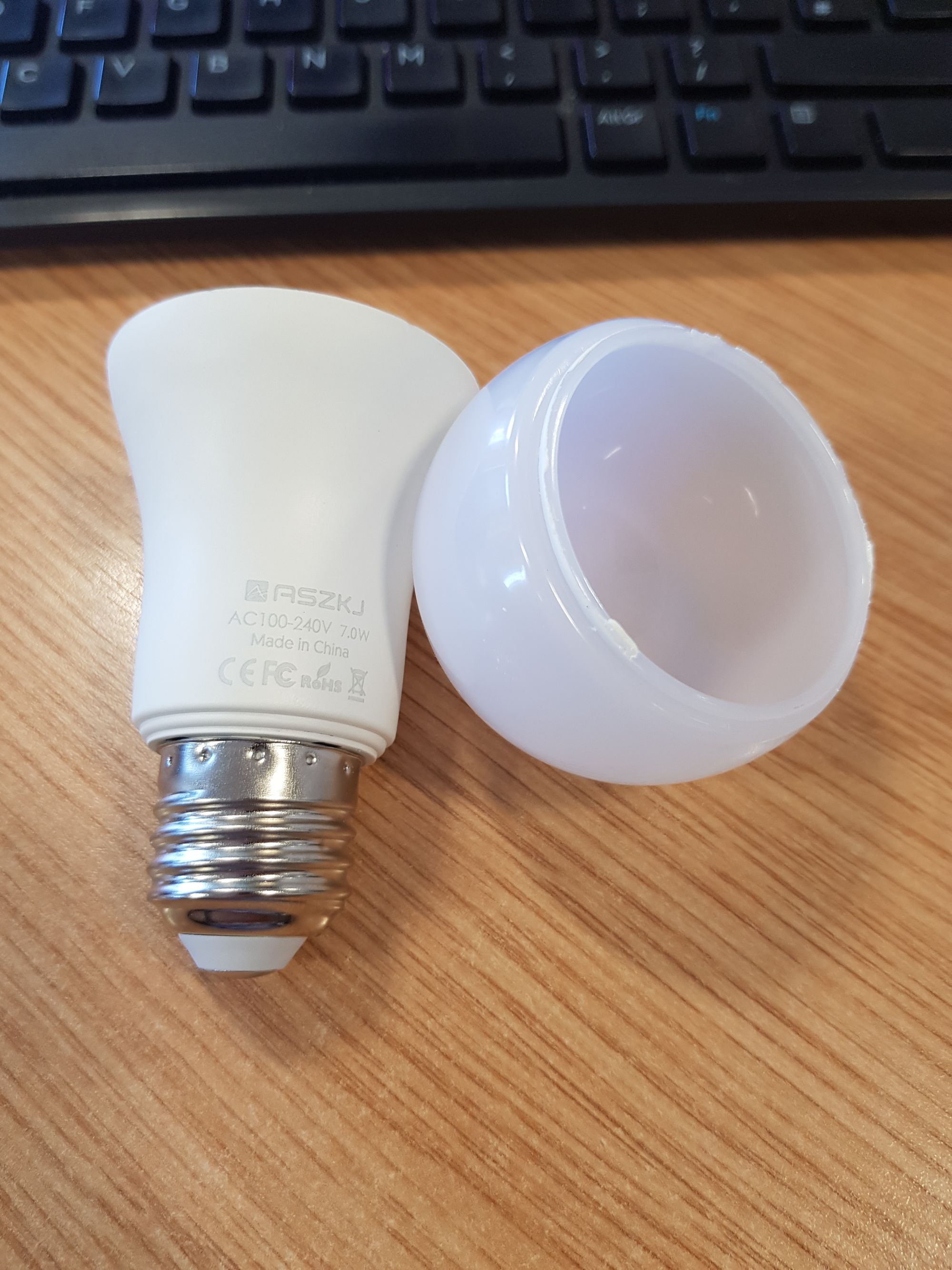
Bulb preparation:
First thing to do is pull the plastic globe/dome from the top of the bulb, the easiest way I found was to twist first to loosen the tiny amount of glue that has been applied, then mine just pulled straight upwards with very little effort.
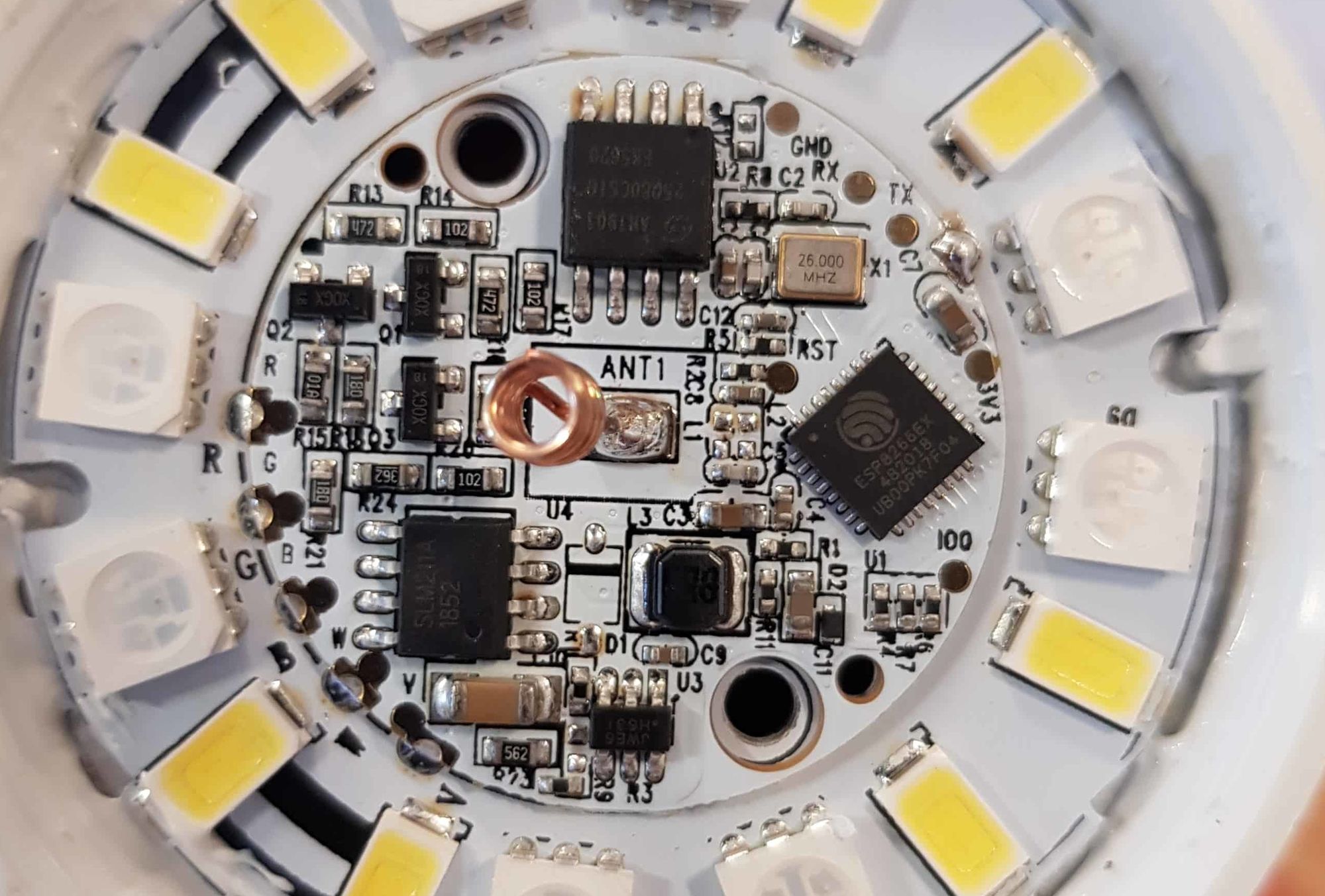
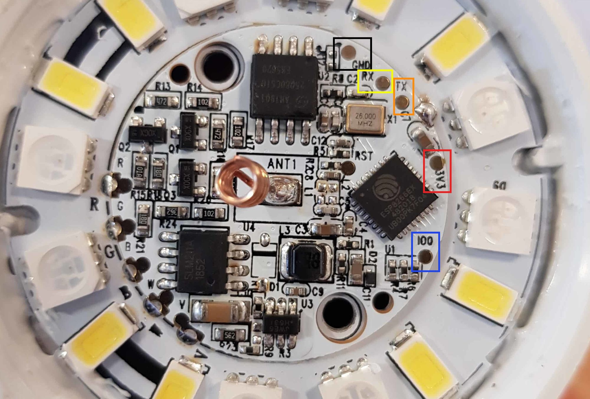
Now we have direct access to the PCB. If we look closely at the chip, we can confirm that the chip we are working with is indeed an esp8266:
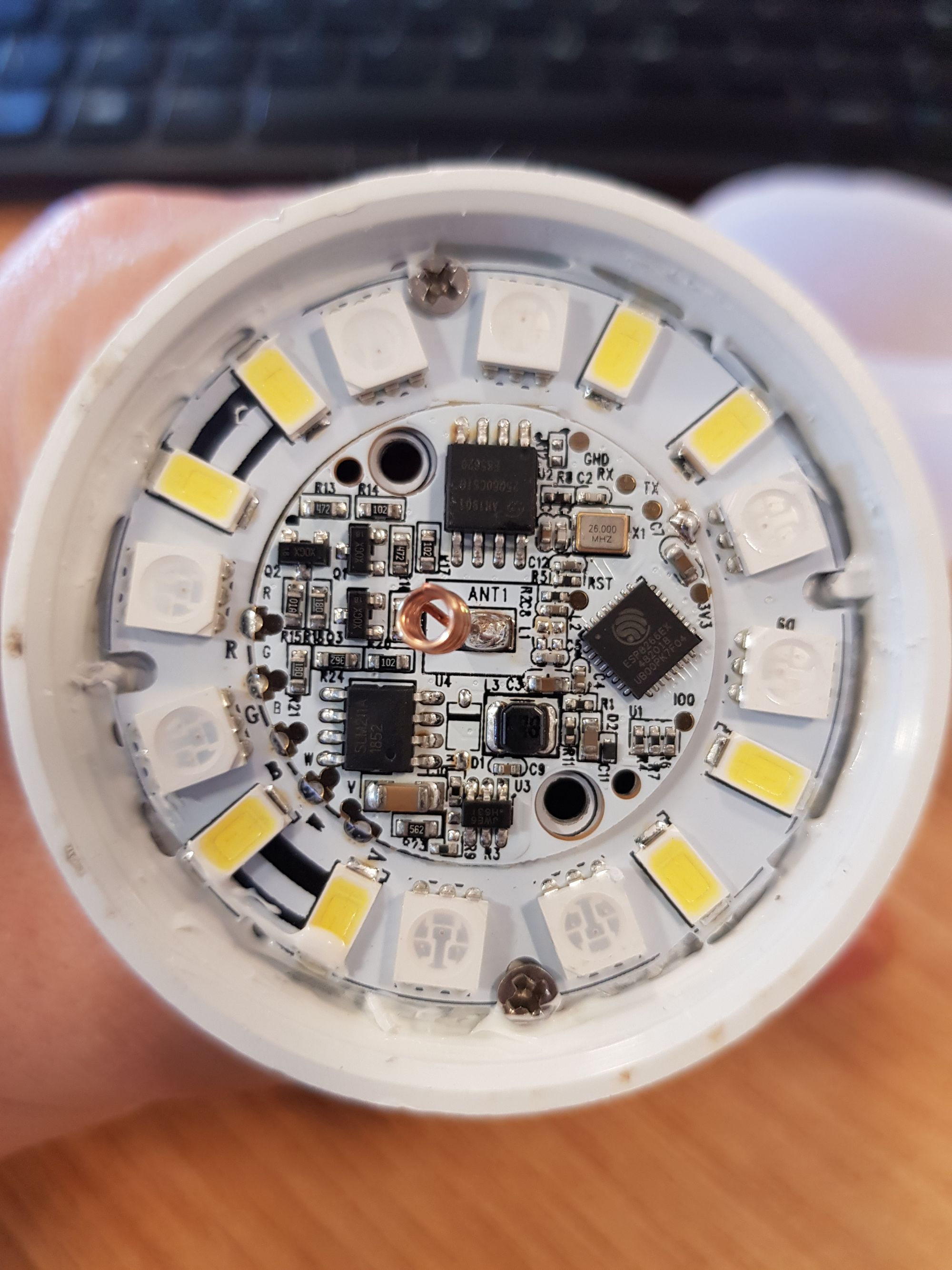
We can then start identifying where we need to solder our wires. You need to identify the following points on the board:
- 3.3v
- Ground
- IO0
- TX
- RX
I’ve marked these on my bulb, these may be the same location on yours or slightly different. They should have markings on the PCB which identify these points:
Go ahead and carefully solder these connections, they are quite small and may require a bit of patience.
Once you have your connections, go ahead and wire them up as follows:
One very important final step here, make sure you have the jumper on your USB to serial adapter set to 3.3v and NOT 5v – I haven’t tried 5v but I assume it would damage your bulb.
Connecting and reading stock firmware
Before continuing, you read the paragraph above right? Please make sure you have your USB to serial adapter set to 3.3v.
Also take this final opportunity to check you have everything wired correctly as above.
Now proceed to plug your USB adapter into your laptop. It should pick up that you have plugged something in.
You will need to have python 2.7 installed, as well as PIP. I won’t go over that here, but there is a nice guide here:
- Windows
- Linux – much easier here, just search your distro and python 2.7 install and follow the guide. Takes 2 minutes max.
Once you have python installed, run the following command in command prompt or terminal to install esptool:
pip install esptoolTyping “esptool” on its on should confirm it is installed.
We then need to check our which COM port we are using.
To do this on Windows, right click the start menu and choose device manager. It should bring up the device manager window. Scroll down to the “Ports (COM & LPT)” section and expand. Find the entry that has “USB-to-Serial” in the name, it should have a COM Port in brackets at the end. The screenshot below shows that mine is COM4.
Linux users, again depends on the distro but you should be able to type the following command, you can see that mine is ttyUSB0:
dmesg | grep tty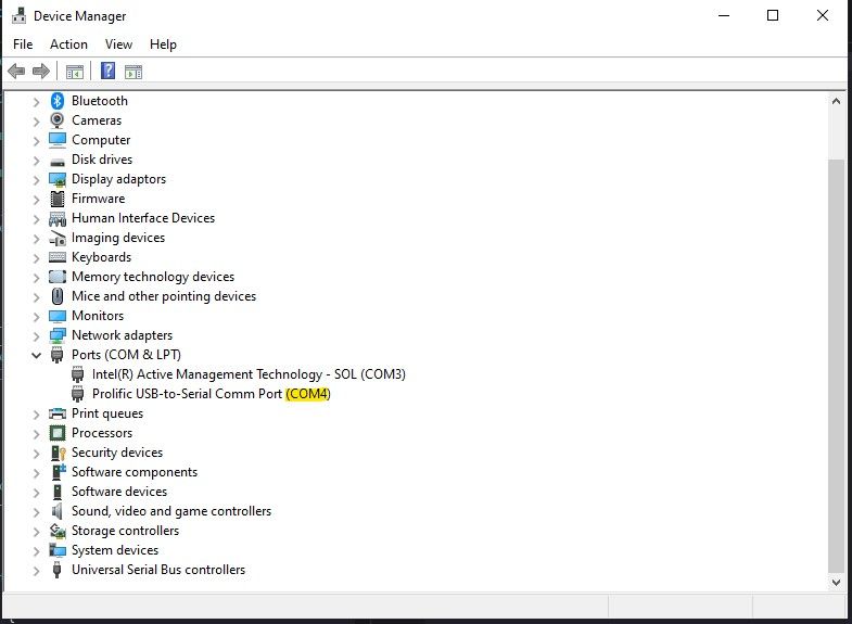

With that out the way, we go back to our esptool terminal. The following command instructs esptool to read the flash memory of our bulb and store it so that we have a backup of our original firmware which can be kept if you want to go back to the original firmware.
To do so, run the following in command prompt/terminal:
Windows:
esptool --port YOUR_COM_PORT --baud 115200 read_flash 0x00000 0x400000 backup.img

Linux:
esptool --port /dev/YOUR_COM_PORT --baud 115200 read_flash 0x00000 0x400000 backup.img
Ensuring to replace “YOUR_COM_PORT” with your COM port as we noted above. So for me it would be “COM4” for Windows or “/dev/ttyUSB0” for Linux.
This can take a few minutes to complete so sit tight. Once complete you should have a full firmware backup file, keep this safe if you want to use it again in the future.
Creating an ESPHome firmware
You’ll be glad to know we should be on the home stretch, if you’ve made it this far then the hard work is done.
I’m going to be using esphome in this example, as I like the integration with Home-Assistant. Let me know if you want to see a Tasmota example.
Back in your terminal, we need to install esphome to create a firmware for our smart bulb. This is done simply with pip again:
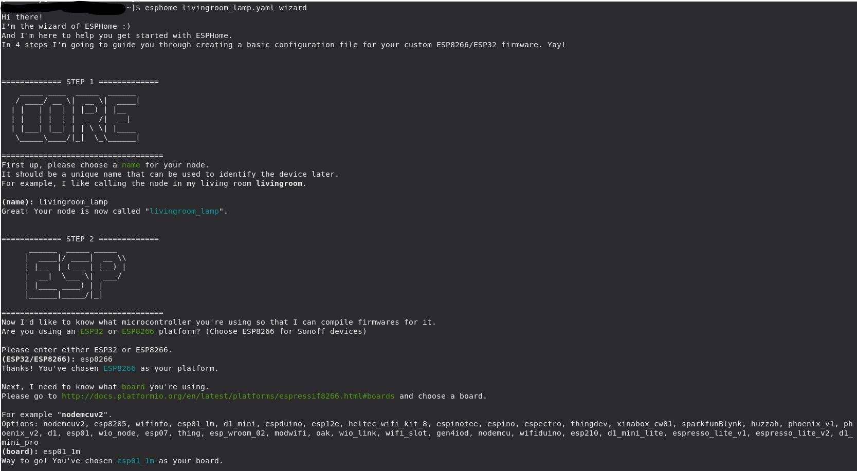
pip install esphomeThen we run the esphome wizard to create a new project:
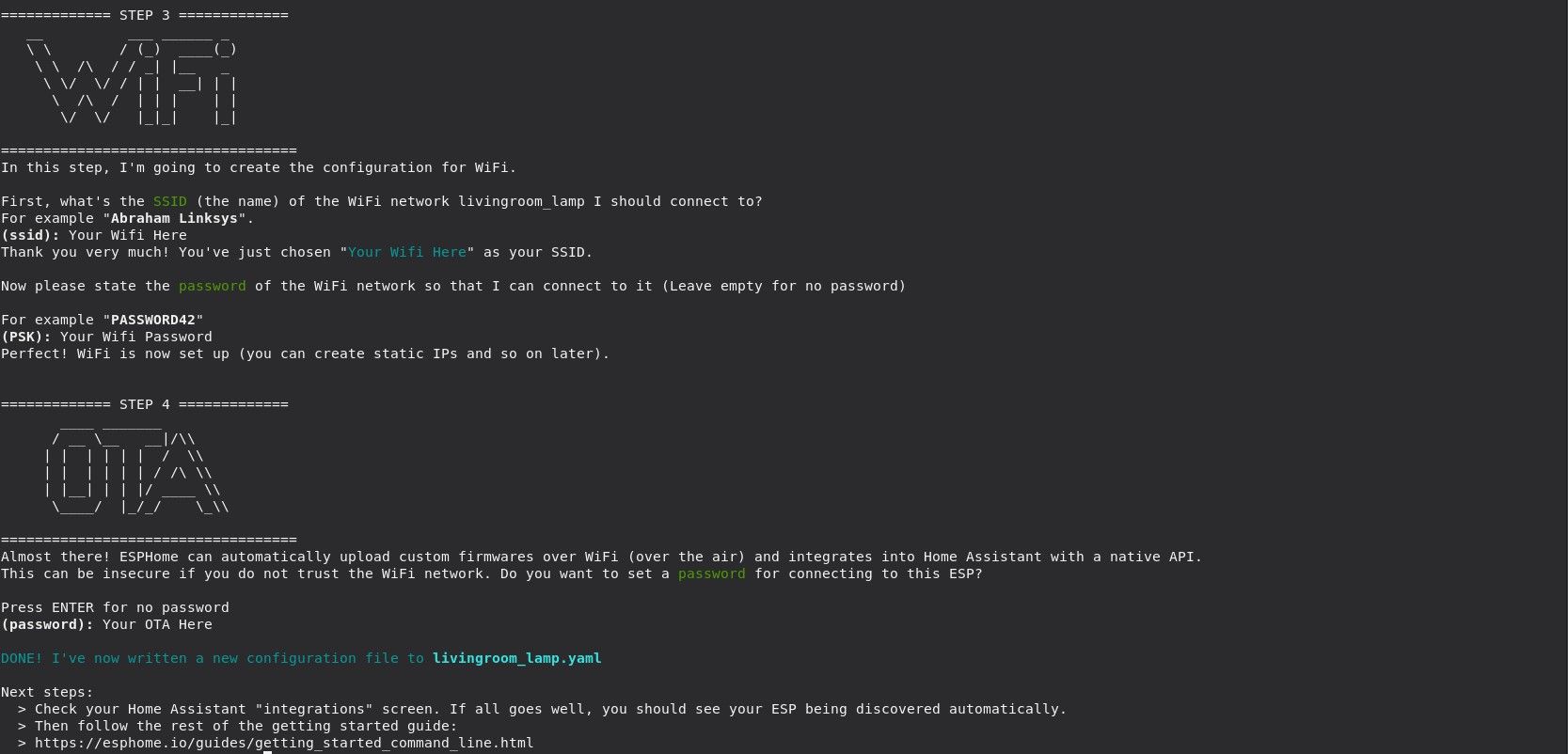
esphome livingroom_lamp.yaml wizardThis will run the wizard which will create a basic configuration for you. Follow the steps through and answer each question, make sure to choose esp8266 as the platform and esp01_1m as your board. Also make sure and set your wifi correctly, as well as the password you want to use for OTA updates.
OTA updates stands for “Over the air” updates which allows you to remotely flash your device without having to go through this whole procedure everytime, no solder required, just a single laptop!
You will now have a file with whatever name you chose above, “livingroom_lamp.yaml” in my case. Open this in your favourite editor, it should look something like this:
esphome:
  name: livingroom_lamp
  platform: ESP8266
  board: esp01_1m

wifi:
  ssid: "Your Wifi SSID Here"
  password: "Your Wifi Password Here"

# Enable logging
logger:

# Enable Home Assistant API
api:
  password: "Your OTA Password Here"

ota:
  password: "Your OTA Password Here"
Be aware when it comes to yaml files that spacing and indentation is import, similar to Python if you are familiar with that.
All we need to do is to add a “light” section and an “output” section. Copy and paste the following to the end of the file:
light:
  - platform: rgbw
    name: livingroom_lamp
    red: output_red
    green: output_green
    blue: output_blue
    white: output_white
    restore_mode: ALWAYS_ON

output:
  - platform: esp8266_pwm
    id: output_red
    pin: GPIO14
  - platform: esp8266_pwm
    id: output_green
    pin: GPIO12
  - platform: esp8266_pwm
    id: output_blue
    pin: GPIO13
  - platform: esp8266_pwm
    id: output_white
    pin: GPIO4
I would also personally modify the wifi section so that you can set a static IP. This is optional, I just think it makes the OTA updates be more predictable. If you want to do that, you can modify the wifi section as follows:
wifi:
  ssid: "Your Wifi SSID Here"
  password: "Your Wifi Password Here"
  manual_ip:
    static_ip: 192.168.0.50
    gateway: 192.168.0.1
    subnet: 255.255.255.0
    dns1: 192.168.0.1
Be sure to change the values for your network, if you don’t know these then I would skip this step.
Flashing/Uploading
Finally its time to upload our work!
Back in your command line window, making sure you are in the same directory as the YAML file you just created, now issue the following command:
esphome livingroom_lamp.yaml runESPHome will now compile the YAML file into a firmware (.bin) file that we can upload and install to our smart bulb. This can take several minutes so wait for this to complete. Once this happens, the command will give you an option:

We choose option number 1, to upload via the serial COM port.
At this point, we just need to wait for the file to upload and we are done!
Once the program confirms the upload was successful, you can now give it a test!
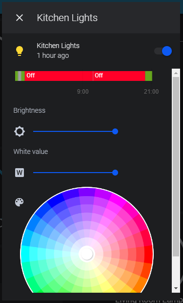
Home Assistant should automatically discover the new light and you should be up and running in seconds. You should then see something similar to this in Home Assistant:
And that’s it! Please leave any comments or feedback down below, as well as anything you want to see in the future!