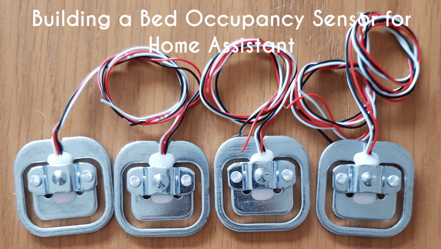
Building a bed occupancy sensor for Home Assistant

Recently after automating many of my lights with motion sensors (guide here) I found myself wanting a way to automatically switch everything off at night. The question was how to properly determine when my partner and I had went to bed for the night?
I started researching bed occupancy sensors and came across a great post from Zack at Self Hosted Home where he used an ESP8266, 4 load cells and a HX711 to build what is essentially a bed size weight scale to determine if someone was in bed or not. I decided I needed to build the bed occupancy sensor and integrate it with Home Assistant.
However when I set about building this, I ran into a few issues that required my setup to be different:
- How to connect 3 wire load cells, there are a lot of cheap 3 wire sensors out there but much of the documentation is for a proper 4 wire setup. Although to be clear, the post above does use a 3 wire setup also.
- Load Cell drift – once I had the setup working, I found my values would slowly start to drift over the course of a day and I wanted a way to overcome that.
- Using an exact weight rather than raw scale values – Zack uses the raw scale values in his setup rather than a calculated weight. This works great for his setup but my sport means that my weight can intentionally fluctuate quite a fair bit. For this reason I wanted to use a calculated weight in KG rather than the raw value, to make tuning my setup easier.
I also 3D printed some holders for the legs of my bed which are a little bigger than normal, these hold the sensors in place and stop the bed sliding around on them which I found was happening and causing issues with my readouts!
Let’s get into building a bed occupancy sensor for use with Home Assistant, or any home automation platform!
Parts list
There are just 3 essential parts for this build:
- HX711 Amplifier
- Load Cells – Note a HX711 is included in this link, I tried this one but the SparkFun one is of better quality and less fluctuations. Your mileage may vary!
- Wemos D1 Mini or other similar board, needs 5V output.
Optionally you may want to print some holders for the cells if you have a 3D printer available and depending on your setup. There are many designs available on Thingiverse.
Guide
Video
Here is a video guide if you prefer:
Hardware setup
These load cells are essentially a series of resistors whose value changes when flexed, the resulting change in voltage can then be measured and transformed into scale readings.
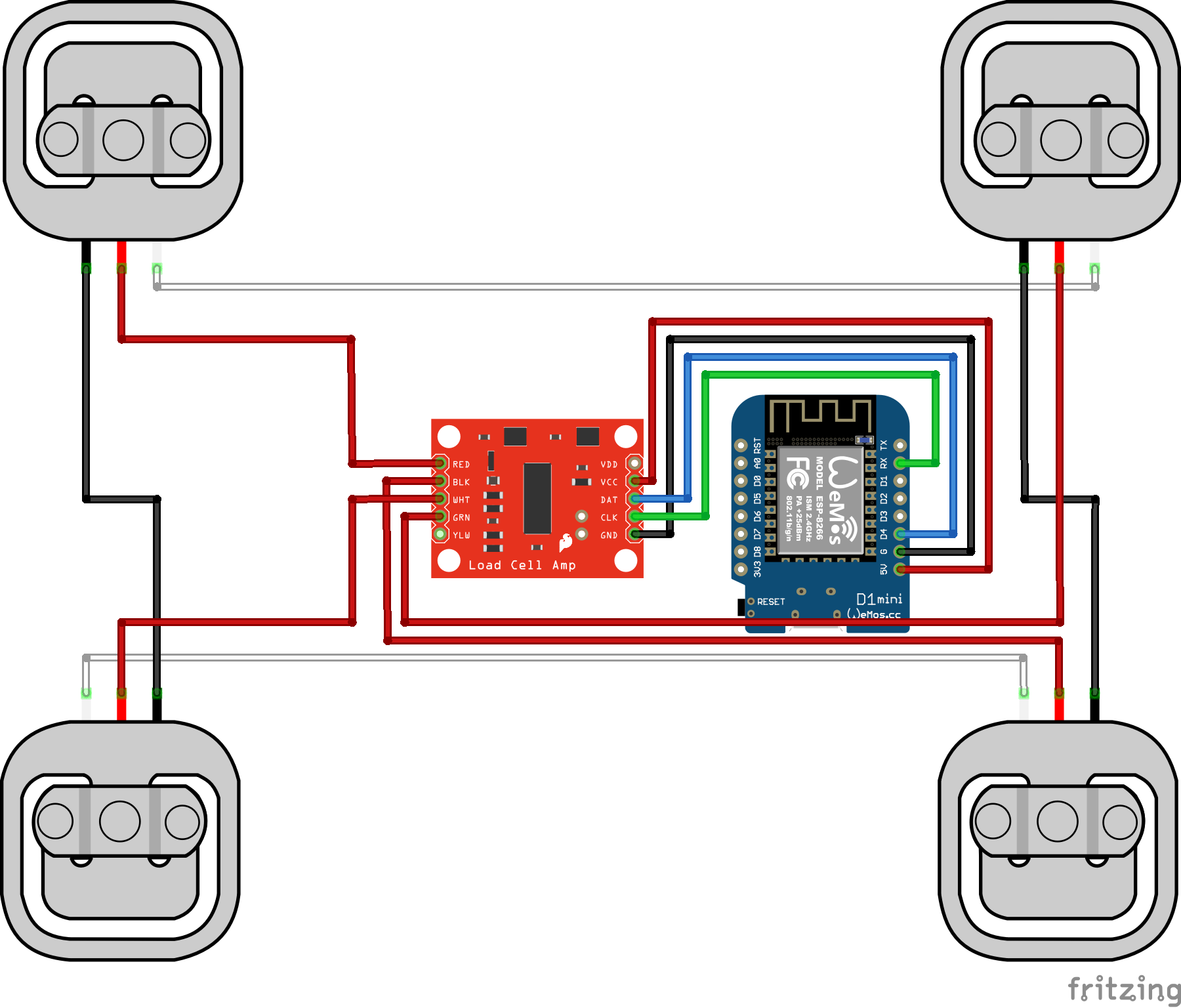
We are going to be connecting the load cells in a full wheatstone bridge in this guide which uses 4 load cells, however it is possible to use 2. The wiring for this can be a little confusing on first glance.
Firstly identify the following connections on your HX711 board, E+, E-, A+, A- (sometimes A is called S so interchange these).
The easiest way to start out is to lay all 4 load cells out into a square shape with one in each corner. You will have an Upper Left, Upper Right, Lower Left and Lower Right. In a very basic sense, the white wires join horizontally, the black wires join vertically and the red wires go to the HX711.
Upper left should go to E+, lower right should go to E-, upper right should go to A+, lower left should go to A-.
Once you have that, we need to wire the HX711 to the our Wemos D1 Mini (or whichever board you are using). Wire the 5v output of your board to the VCC pin on the HX711, do the same with the ground pins. Then we take the pin labelled D4 on our board and wire it to the DAT pin of the HX711. Finally, RX pin of our board goes to CLK of the HX711. We are using pins 2 and 3 in our code which corresponds to D4 and RX on our ESP board (GPIO 2 & 3).
It should look like this:
Software
We are going to be using the HX711 library, found here on Github.
Go ahead and fire up Arduino IDE and set your board to the Wemos D1 Mini (or whichever you are using) – set your board speed to 74880 for the D1 mini otherwise you may get some weird characters which seems to be a known issue.
Go to Sketch > Include Library > Manage Libraries and search for HX711 and install it.
Next download both of the sketches from my Github for this project, located here. These use MQTT so that our bed occupancy sensor can speak to Home Assistant.
Test run
At this point I’d highly recommend testing everything is working before going to any effort of mounting.
Go ahead and upload the “Scale Calibration” sketch to your board and open the serial monitor at 74880. After a few seconds, you should see the monitor start to output something that resembles the following:
Initializing scale calibration.
Please remove all weight from scale.
Place known weights on scale one by one.
Reading: 0.00kg
Calibration Factor: 2400
Reading: 0.00kg
Calibration Factor: 2400
Reading: 0.01kg
Calibration Factor: 2400
Reading: 0.00kg
Calibration Factor: 2400
Reading 0.00kg
Calibration Factor: 2400
If you are getting readings from the monitor then this should mean your setup is working. If you are not, check your wiring as per above and check the troubleshooting section below.
Put some pressure on the inner part of one of the load cells with your finger, you should then start to see values change:
...
Reading: 0.01kg
Calibration Factor: 2400
Reading: 0.00kg
Calibration Factor: 2400
Reading 0.00kg
Calibration Factor: 2400
Reading: 4.58kg
Calibration Factor: 2400
Reading: 4.02kg
Calibration Factor: 2400
Reading 4.27kg
Calibration Factor: 2400
...
Don’t worry about the actual values, we will calibrate properly later.
Mounting
Assuming you got readings as above, you should be safe to mount the hardware in its final position.
This part is obviously very person dependant, but I’ll show you how I mounted mine.
Originally I had tried a number of different 3D printed holders for the load cells, they all worked but I found due to the nature of the legs of the bed, that the bed would very easily slide around on top of them meaning that the values would change daily which was very frustrating when trying to get a consistent setup!
The other issue was when manually placing the sensors under the bed, it was hard to get them in the same position under the bed at each corner, so that one sensor did not have more or less weight on it than another corner.
So I spent 20 minutes 3D modelling some casters/holders for the legs of my bed, so that the sensors would always be in the same position and the bed was unable to move.
Here was what I came up with:
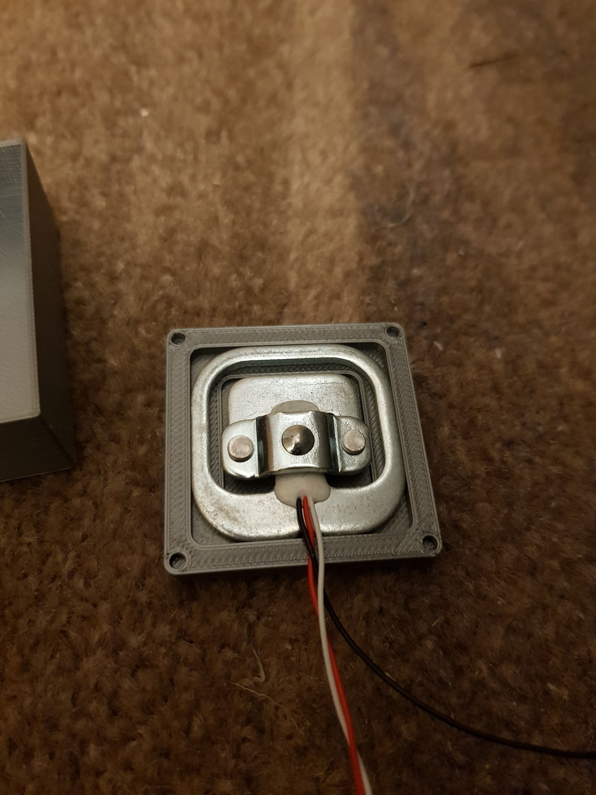
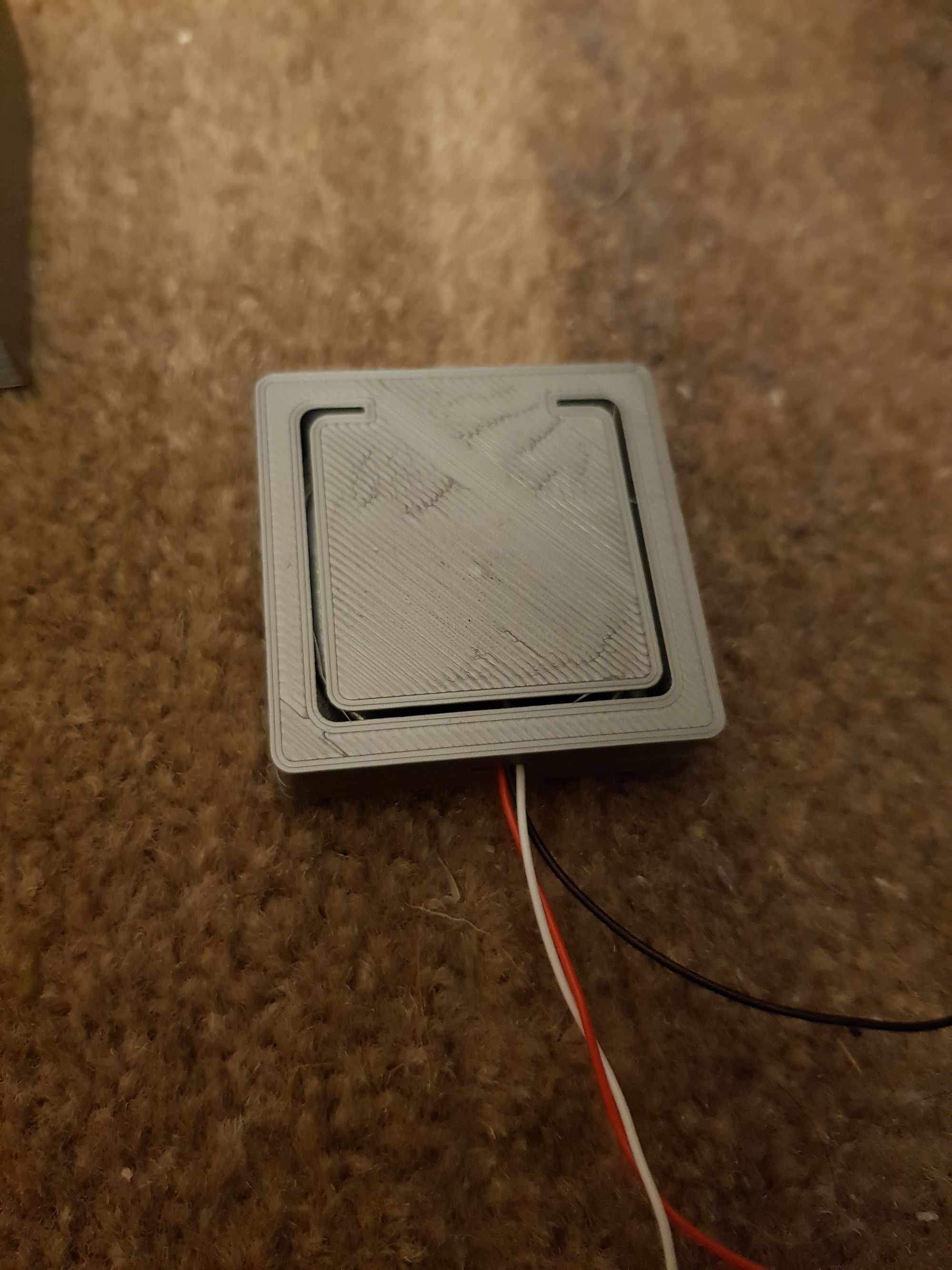
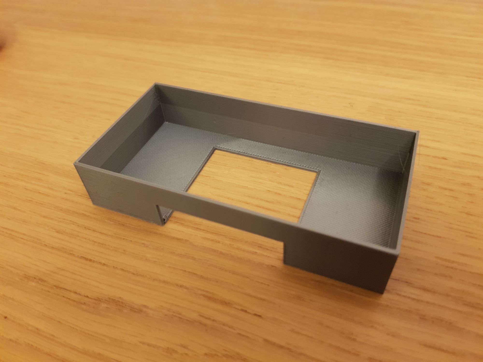
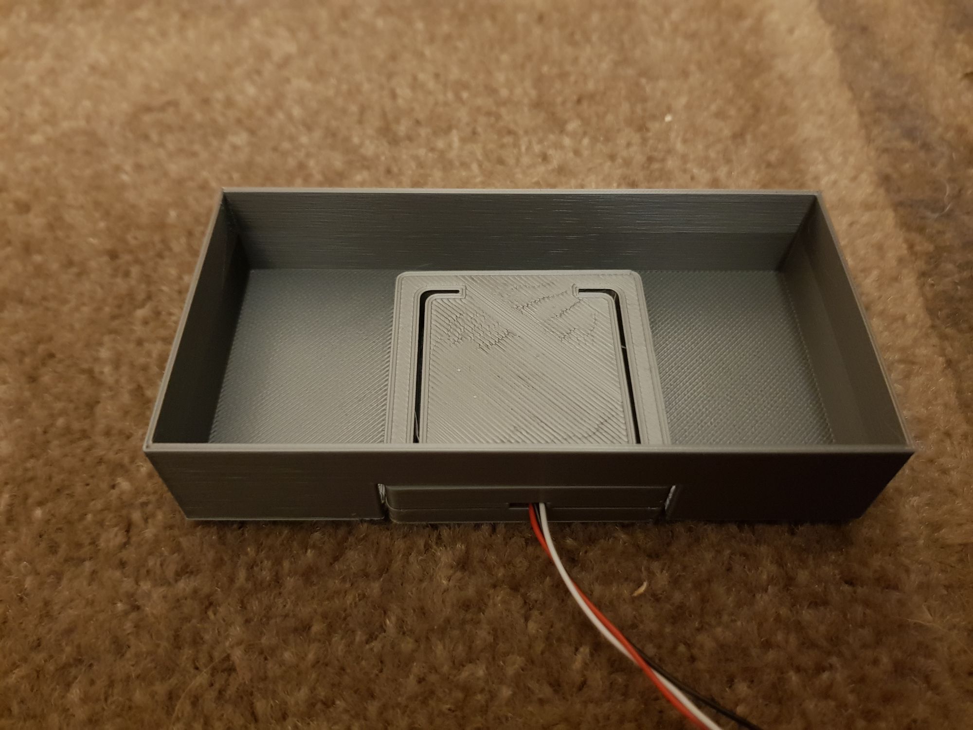
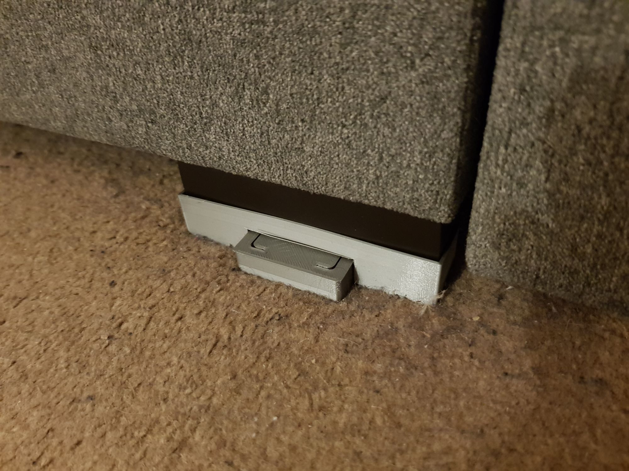
This design allows the legs of the bed to sit perfectly inside and allows for zero movement of the load cell, meaning each corner is weighted identically.
Once mounted, we can move onto calibrating the scale for your setup.
Calibration
To get the load cells calibrated for your setup, ensure there is no additional weight on the scales apart from what would normally be on there at a “zero weight” – duvet, pillows etc.
We can fire up the calibration sketch again and open the monitor at 74880.
- Allow the monitor to print the zero weight a couple of times, again this should be 0 kg or very close to it. Expect a little fluctuation, this is normal.
- Once this has settled, place a known weight on the scale, 5kg is a good weight to use. Observe the output on the monitor and see how close (or far!) it is from being correct.
- Adjust the “calibration_factor” variable in the code and re-upload – start by adjusting the factor with larger increments of say 500 till you start to get closer to the actual weight, then maybe 100 points then 10 points.
- Re-upload the code – don’t forget to take your known weight off each time. Keep repeating until you have an accurate reading.
Once you are happy with the reading, take note of your calibration factor, we will need it for the next section!
Bed Sensor
We can now take a look at the final sketch, the Bed Sensor, which is the one that will integrate our bed occupancy setup with Home Assistant.
Fire up the sketch, and open the change your view to the config.h file:
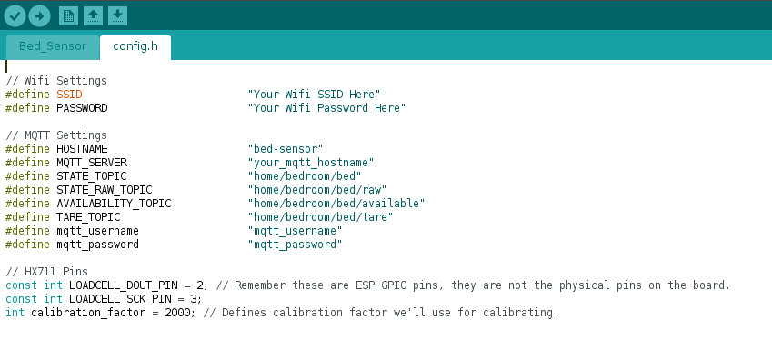
We need to change a few simple variables here:
- SSID and Password – change these to your Wifi setup.
- MQTT_Server – change this to the IP or hostname of your MQTT server.
- mqtt_username and mqtt_password – change these if you have authentication enabled.
- Calibration factor – change this to the value you obtained from the calibration steps in the last section.
You can optionally adjust the MQTT topics if you wish. These topics are for:
- State topic: this is where the kg value will be published to, which will be picked up with Home Assistant.
- State raw topic: I am also publishing the raw scale values to Home Assistant, these can be pretty useful for checking drift.
- Availability topic: When the scale starts up, it will publish a message to this topic so Home Assistant knows it is online.
- Tare Topic: The scale will subscribe to this topic, when it receives a message to this topic, it will tare (reset) the scale. Very useful for combating drift.
Upload the sketch to your board and open the monitor at 74880 speed. You should see it connect to your Wifi, connect to MQTT then it will tare the scale. Then it will start to output the weight and raw value every 3 seconds.
Once again, make sure that no additional weight is on the bed when powering on.
Place a weight on the bed again as a final test and make sure it is reading correctly.
Now we can finish integrating our bed occupancy setup in Home Assistant!
Home Assistant
Open your configuration.yaml file and add a new entry:
sensor:
- platform: mqtt
name: "Bed"
state_topic: "home/bedroom/bed"
unit_of_measurement: "kg"
availability_topic: "home/bedroom/bed/available"
- platform: mqtt
name: "Bed Raw"
state_topic: "home/bedroom/bed/raw"
unit_of_measurement: "raw"
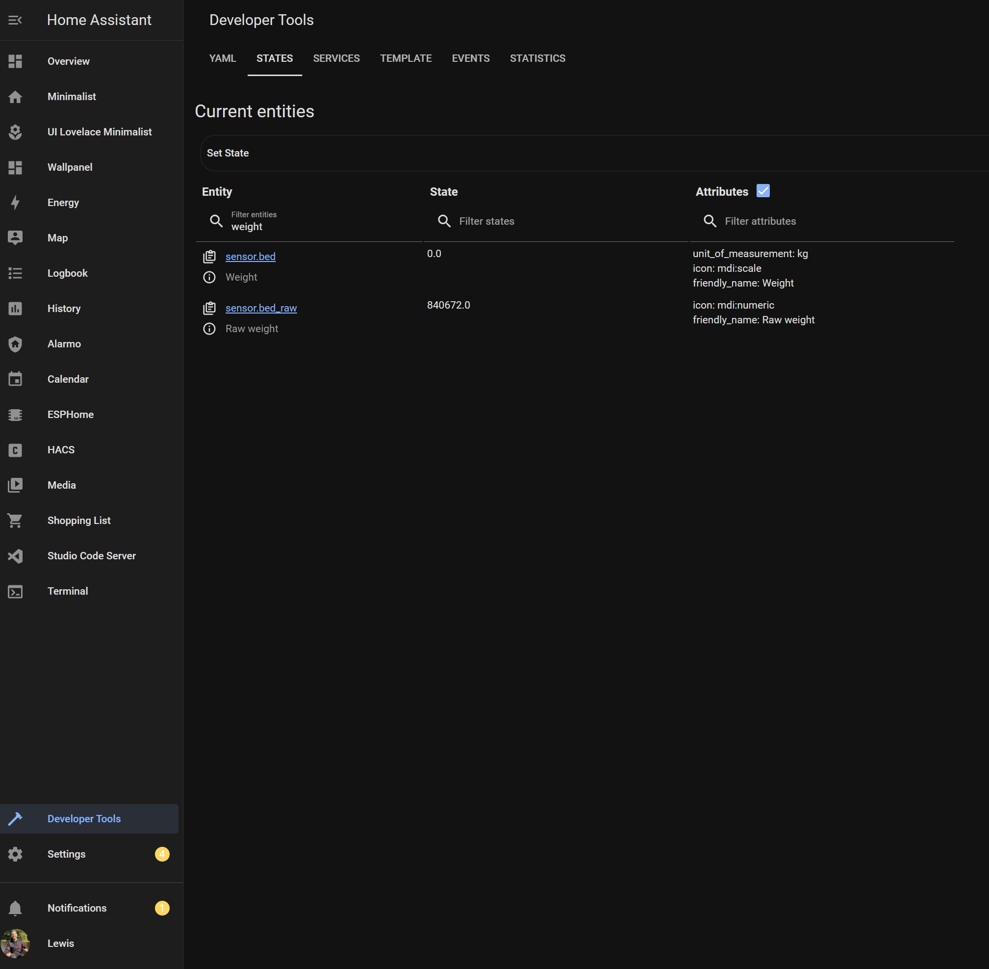
availability_topic: "home/bedroom/bed/available"Reload Home Assistant and go into Dev Tools > States and see if you are getting information through:
Head back to your configuration file and we are going to make some template sensors based on these values. I am using Zack’s code here as it works well.
First we add some template binary sensors:
binary_sensor:
  - platform: template
    sensors:
      lewis_in_bed:
        friendly_name: "Lewis in Bed"
        value_template: >
          {{ states('sensor.bed')|float >= 70 }}
      she_who_must_be_obeyed_in_bed:
        friendly_name: "She who must be obeyed in Bed"
        value_template: >
          {{ states('sensor.bed')|float > 40
            and (states('sensor.bed')|float < 60
               or states('sensor.bed')|float >= 100 )}}
This does a couple of checks:
- If the weight is greater than 70kg, Lewis is in bed.
- If the weight is greater than 40kg, but less than 60kg, she who must be obeyed is in bed. Or if the weight is greater than 100kg, she is also in bed.
I found using a slight range works well.
Then we add another template sensor to calculate the number of people in bed, which is a great sensor to have when doing automations:
sensor:
  - platform: template
    sensors:
      num_in_bed:
        friendly_name: "Number of People in Bed"
        unit_of_measurement: 'people'
        value_template: >-
          {% if is_state('binary_sensor.lewis_in_bed', 'on') and is_state('binary_sensor.she_who_must_be_obeyed_in_bed', 'on') %}
              2
          {% elif is_state('binary_sensor.lewis_in_bed', 'on') or is_state('binary_sensor.she_who_must_be_obeyed_in_bed', 'on') %}
              1
          {% else %}
              0
          {% endif %}
Restart home assistant and check your dev states again.
Time to give it a test and see if the results are as expected. It will probably take a little tweaking to get it correct for your setup.
Next steps
Remote taring
If you find your setup is working, but the perhaps the values are drifting over the course of a day, or the scale isn’t always going back to zero after getting up in the morning, you can use the remote tare function.
One method is to create an automation within Home Assistant which tares the bed occupancy sensor everyday at midday:
automation:
  alias: Remote tare
  trigger:
  - at: '12:00'
    platform: time
  condition:
  - below: '1'
    condition: numeric_state
    entity_id: sensor.num_in_master_bed
  action:
  - data:
      payload: 'on'
      topic: home/bedroom/bed/tare
    service: mqtt.publish
This will reset the scale to zero everyday at midday, only if the number of people sensor is at 0.
Useful automations
A couple of really useful automations using this sensor are:
- Ensuring that when we are both in bed, every light and media player is turned off, door locks are set and the house alarm is set to “armed home”.
- I have lights that are automated through Home Assistant when motion is detected, I add a condition to these automations not to trigger these lights when we are both in bed, this is so that our dogs do not trigger lights all night.
- During night hours, the bathroom light comes on at a very dim brightness if one of us exits the bed during the night. This is great for not being blinded when getting up to the bathroom during the night!
Troubleshooting
- The vast majority of issues will be wiring related. If you are having issues I’d suggest double checking your wiring, then triple checking. Its very easy to make the slightest error which will cause the whole setup to not work correctly.
- Ensure you are using 5v output, 3.3v will technically work, but it is not recommended and you won’t get great results if you don’t use 5v.
- Ensure you are using the correct pins on your dev board. Do not make the mistake of thinking pin 2 and 3 in the code corresponds to D2 and D3 physically on the board. Look up the pinout and ensure you are using GPIO pins.
- Check your voltages, if you have everything correct use a multimeter and measure volts across E+ and E- where you should get 4.3v. Then measure A+ and A- where you will get roughly half of that. If you are not, check your wiring again.
- If you are getting readouts but they are in negative values, switch the E+ and E- wires around and that should correct the issue.
- Solder and heat shrink your wires, they seem to be highly sensitive to interference so do everything you can to minimize this.
Let me know in the comments if you have any further issues or as always, what you want to see next!