Converting the 28BYJ-48 stepper motor for more torque!

A couple of days ago I decided to strip apart my blinds and figure out how to automate them, its something I wanted to do for a while but never really got round to it. Just a couple of hours later, I had something functional and working as you can see here:
Finally got around to figuring out how to make some motorised blinds with @esphome_ and @home_assistant pretty happy with how these work just now!#iot #homeassistant #homeautomation pic.twitter.com/CSxxbFZX9p
— Everything Smart Home (@EverySmartHome) June 11, 2020
To do this I was using a 28BYJ-48 5v stepper motor which is a super common stepper motor for us DIY enthusiasts, and I designed a little spooler which pulls the cord either direction.
The problem with 28BYJ-48 is it’s pretty slow in stock form as you can see, and it’s really lacking in power and torque. The latter was very apparent when it came to my blinds, there were a couple of sticking points that the motor could not seem to overcome.
Normally I use NEMA 17 motors where I can, they are a really excellent motor and you will find them in almost every consumer 3D printer on the market. Unfortunately for me, there was absolutely no way for a NEMA 17 to fit inside this blind, the 28BYJ almost doesn’t!
So I really need a way for the 28BYJ-48 to produce more torque, and ideally speed. But how?
After a bit of research I found that the 28BYJ-48 can be converted from its original 5 wire unipolar stepper, to a 4 wire bipolar stepper. This modification allows us to really improve the torque and speed. Some sources state more than 2x the torque! What’s more, its really simple!
Parts List
I’m assuming if you are reading this that you probably already have a motor you want to modify but just in case I’ve listed them below. We are also going to be using the A4988 stepper driver instead of the stock ULN2003 driver:
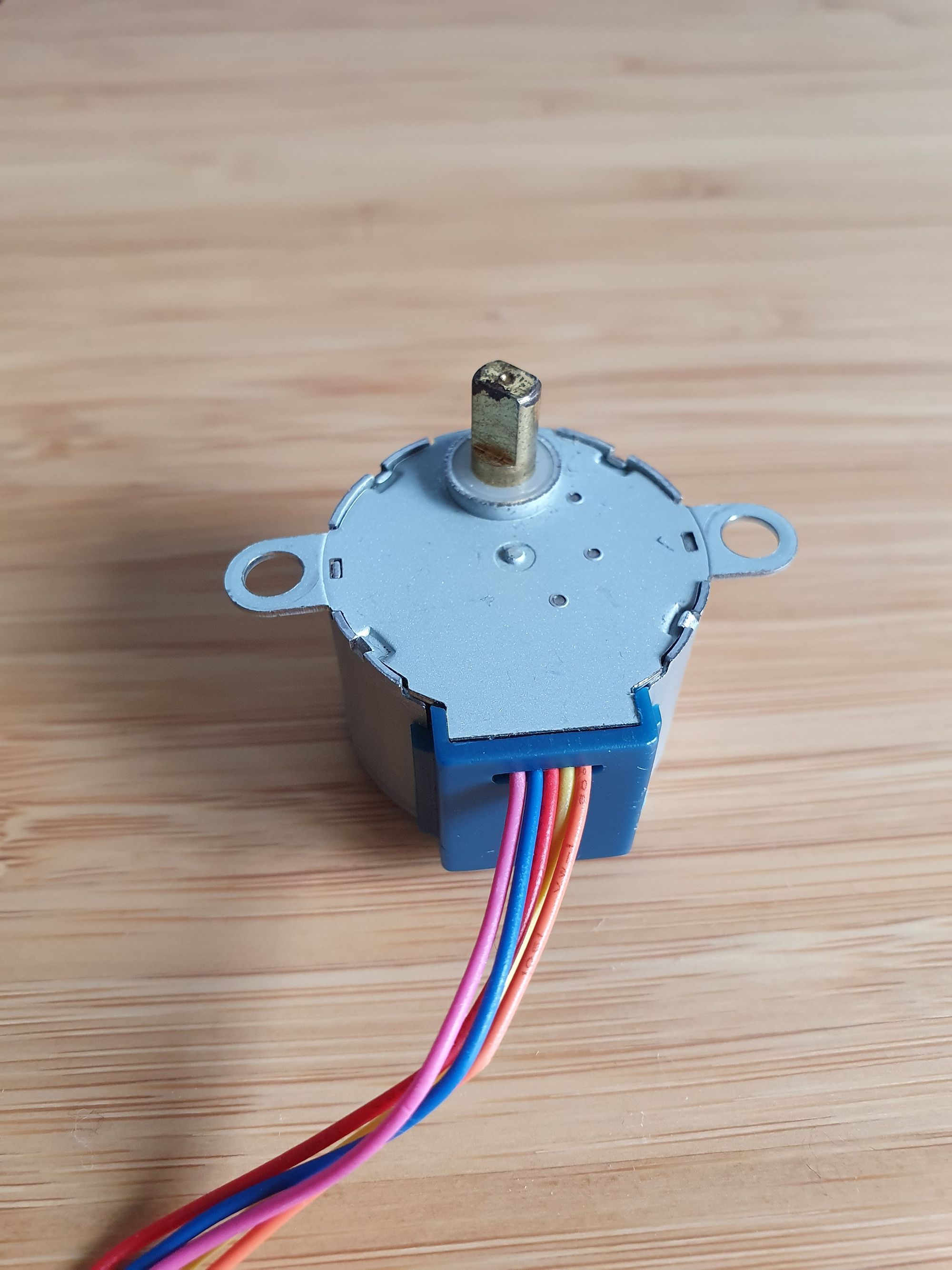
- 28BYJ-48 stepper motor – I am using the 5v here but you can do this with the 12v version.
- A4988 stepper driver
Note there is more parts to this, but this isn’t a guide for connecting it to Arduino or an esp8266 board, we will cover that in the upcoming DIY motorised blinds guide.
Guide
The modification for this is easy…really easy. Most information I can find online involves removing the blue cover on the stepper, and making a small cut to the PCB trace for the red (5v/12v) wire. I went ahead and did this on my first attempt and it does indeed work as intended.
However.. after I got everything working I tried it without making the cut, so just a stock motor connected to the A4988 board and it worked fine in my testing. I am no electrical engineer. But from what I could test it functions the same, if someone would be able to confirm that would be great.
For the sake of completeness, I’ll show you how to make that cut just in-case you cannot get it to work. Obviously once you do this you will not be able to go back to using the ULN2003 driver. But these motors are so cheap, hopefully that shouldn’t be an issue.
Cutting the trace
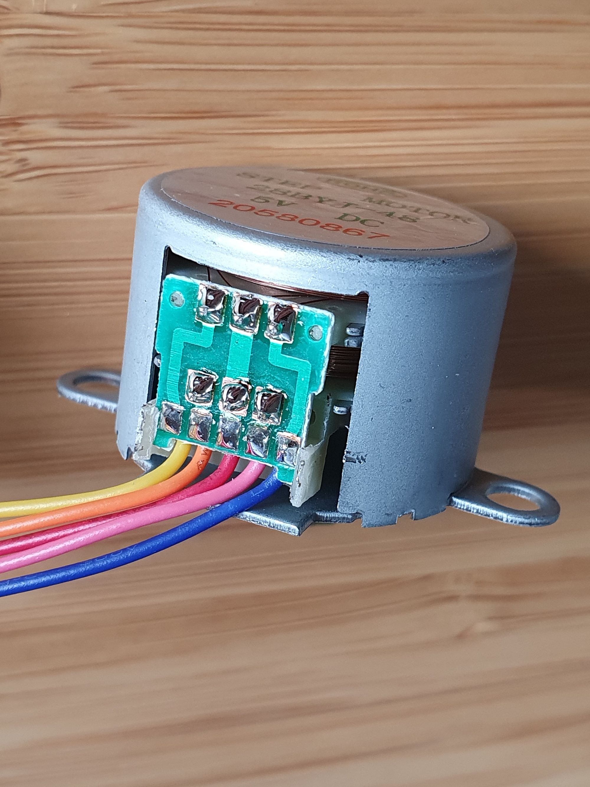
Right where the 5 wires exit the back of the motor, there is a blue cover:
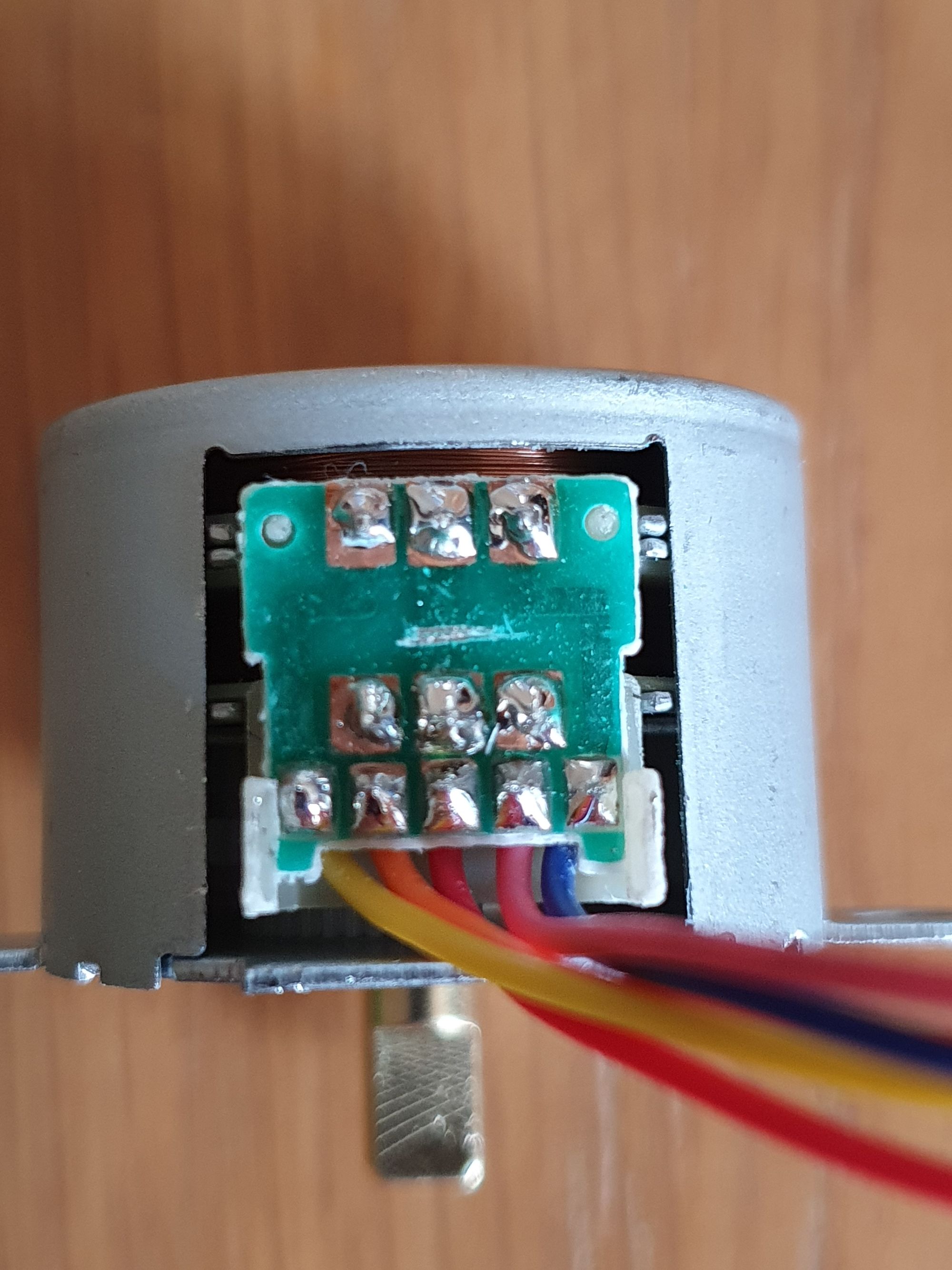
Grab a tiny screwdriver and carefully lever this cover off, it is almost certain you will break one or two clips, this will reveal the PCB underneath:
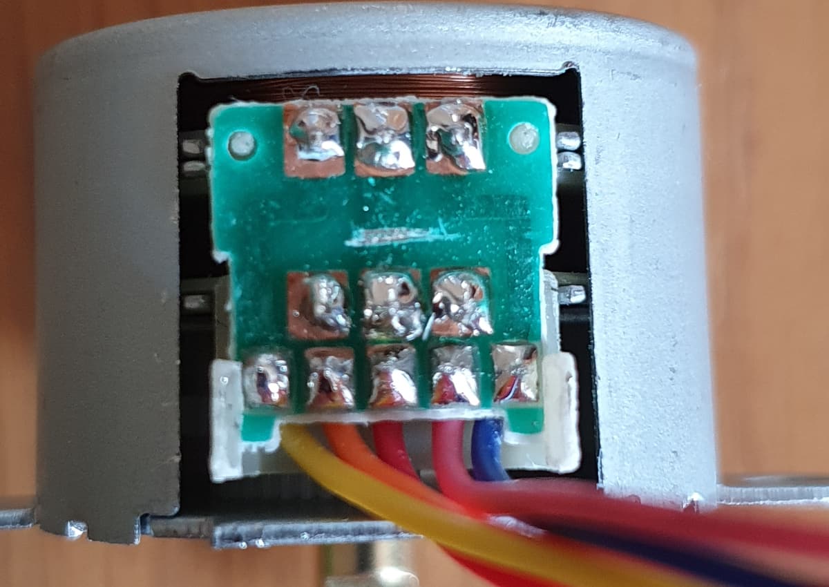
Next, take a Stanley knife or small screw driver and cut the middle trace (where the red wire joins). It might take a few goes, just be patient and slow with it. Here’s the after:
Finally, if you have a multimeter, you can do a continuity check between the centre top and bottom pads to confirm the connection is broken.
You can also remove the red wire if you want but not required. Put the cover back on and you are finished. Now we need to wire the 28BYJ-48 to our A4988 driver and set the current for our torque requirements.
A4988 driver wiring
With the modification completed, we can now wire the 28BYJ-48 stepper to the A4988 (or other) stepper driver.
Take a look at the following wiring diagram:
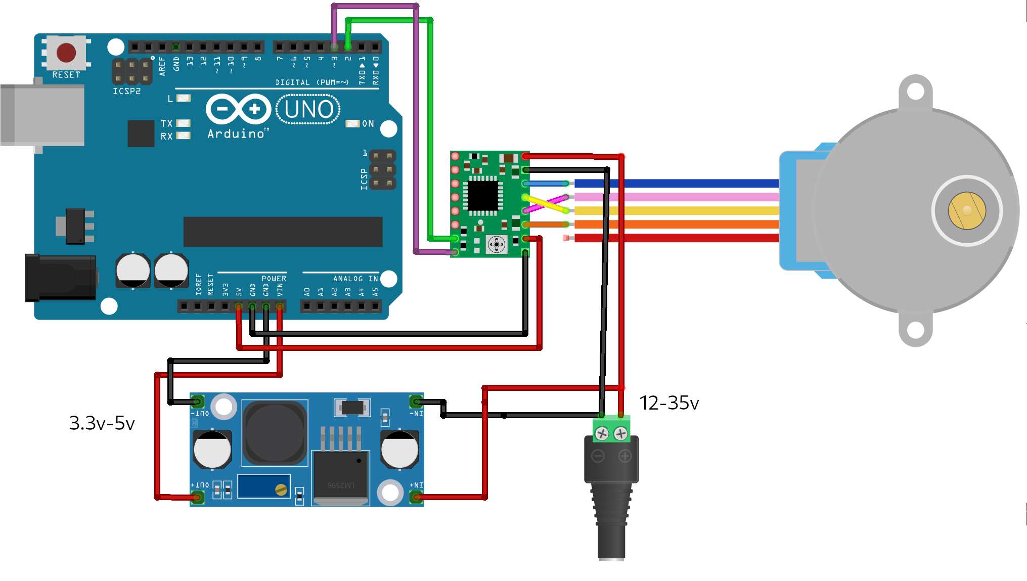
You will notice the A4988 requires a 8-35v input, clearly much more than our Arduino/esp8266 boards are capable of supplying. I’d recommend a LM2596 buck converter and a barrel jack screw terminal as a really easy method.
A few important things to note:
- You must connect the reset and sleep pins together. I like to solder the top of the pins together.
- The orange and pink wires represent coil 1 and should be wired to 1A and 1B on the A4988. The yellow and blue wires represent coil 2 and should be wired to 2A and 2B.
- If you do not require holding torque whilst the motor is inactive, I would highly suggest using the sleep pin, this will drastically keep the heat and power down in both the motor and driver. Speaking of which..
- Use a heatsink with the driver, these things can get hot!
- Do not unplug the motor from the driver whilst powered on, you can very easily damage the driver.
Setting the A4988 current limiting
Finding the rated current for the 28BYJ-48 is quite hard, I wasn’t able to find much information out there, but I found a few bits of information stating that around 0.10v or 0.25ma is fine. If they are going to be used in short and very infrequent bursts (like a blind!) you can probably get away with more but you may damage them.
To set the current limit you will notice a little potentiometer on the A4988 board (this can be pretty fragile!), with everything powered on, you can set your multimeter to DCV and hold the red terminal on the potentiometer and the black terminal on the bottom right (assuming the potentiometer is at the bottom) ground pin, this will give you the current rating:
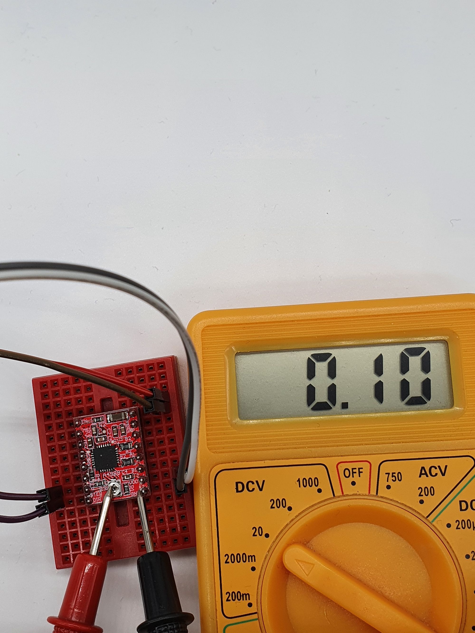
To reduce the current, turn the potentiometer anti-clockwise. Keep turning and re-testing till you are around the 0.10-0.15v value. It’s a very narrow window, a tiny turn on the screw changes the value a lot.
I’d suggest testing with various values to see what works for your application and try to figure out the minimum values you need to get the torque and speed required from your 28BYJ-48 stepper.
Conclusion
There we have it, you can see just how easy it is to convert the 28BYJ-48 stepper motor from unipolar to bipolar to get more torque and speed from it. In my testing it made a massive difference to how powerful the motor was, easily being able to overcome the sticking points my blinds had compared to the stock version that would get stuck frequently.
Give this a try if you wish your stepper had a bit more power and let me know how it goes.
Be sure to subscribe so you don’t miss the DIY motorised blinds or the combined RFID and fingerprint sensor.