Adding an SSD1306 OLED display to any project

Having everything connected over WiFi is great, all the information directly on your phone, tablet or laptop is incredibly powerful but sometimes you just want some information at a glance without having to pull out your phone to check.
Enter these mini OLED displays which feature an SSD1306 driver and are incredibly useful for displaying information at a glance. These 1 inch displays are super compact, cheap, require only 4 wires using the i2c protocol and because they are OLED there is no backlight and aren’t an eyesore in a dark environment.
Today I will show you how to wire an SSD1306 OLED display, add it to any existing project and we will cover some coding examples.
Video
Parts list
There are very little parts we need for this build, just 2 in fact, and one of them being one you probably already have:
- 0.96″ OLED Display – They are available in different colours, I prefer the white one myself as well as different sizes. They feature an SSD1306 OLED display driver with an easy to work with library.
- Arduino Uno, ESP8266 or any similar board that supports i2c.
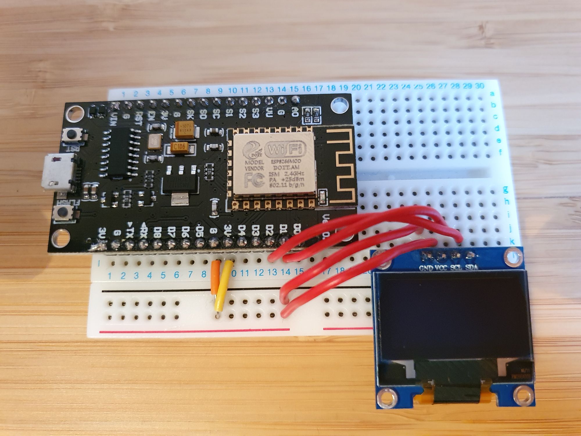
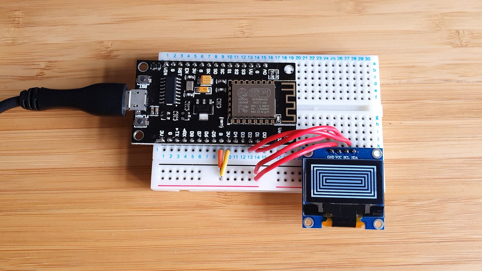
Hardware wiring
The problem with some displays is that they can require a lot of wires to drive – that isn’t a problem here. Just 4 wires are required for these displays, VCC, ground, SDA and SCL.
The first thing we need to find is our boards i2c pins (SDA and SCL). To do this, find the pinout for your specific boards and find the SDA and SCL pins. A couple of common ones are:
| Board | Pins |
|---|---|
| Arduino Uno | SDA and SCL Pins |
| Arduino Nano | A4 (SDA) and A5 (SCL) |
| Arduino Mega | D20 (SDA) and D21 (SCL) |
| ESP8266 NodeMCU | D2 - GPIO4 (SDA) and D1 - GPIO5 (SCL) |
| ESP8266 Wemos D1 Mini | D2 - GPIO4 (SDA) and D1 - GPIO5 (SCL) |
| ESP32 | GPIO21 (SDA) and GPIO22 (SCL) |
Next its simple a case of wiring everything just like this, note that these displays can operate from 3.3v to 5v but double check your exact model:
Discovering the i2c address
Since i2c is a protocol that allows multiple different devices to run over these 2 wires, every device is programmed with an “address” which it can be accessed at in order to differentiate between devices. Think of it kind of like a MAC address. This is how the temperature sensor works from this guide here (which might I add is a great project to add these displays too!)
The first thing we need to do is discover the address our display uses. The easiest and quickest way to do this is simply to use an i2c scanner. In Arduino IDE, go to Tools > Manage Libraries. Search for “i2cdetect” and install i2cdetect by Mike Causer.
Go to File > Examples > i2cdetect > i2cdetect and upload the sketch to your board. Open the serial monitor and you should see the address of your i2c display:
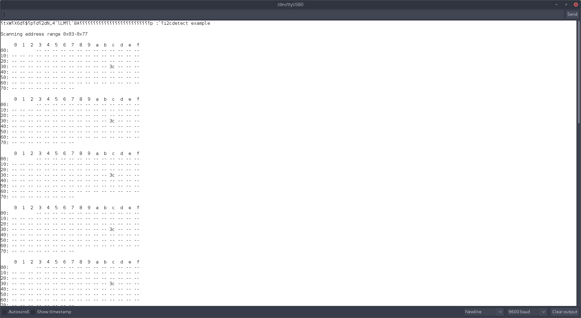
You can see in the above example that my address is 0x37 – remember that as we will need it in a second.
Installing the Adafruit Libraries
Go back to Tools > Manage Libraries, search for “Adafruit SSD1306” and hit install. You may receive a message stating that this library has dependencies and asking if you want to install them also. Hit yes. If you do not get the message, search for “Adafruit GFX Library” and “Adafruit BusIO” and make sure to install them too.
There are other libraries that work with the SSD1306 OLED display but I found the Adafruit one works really well for the basics.
Let’s firstly test out our display is working and wired correctly by loading the Adafruit example.
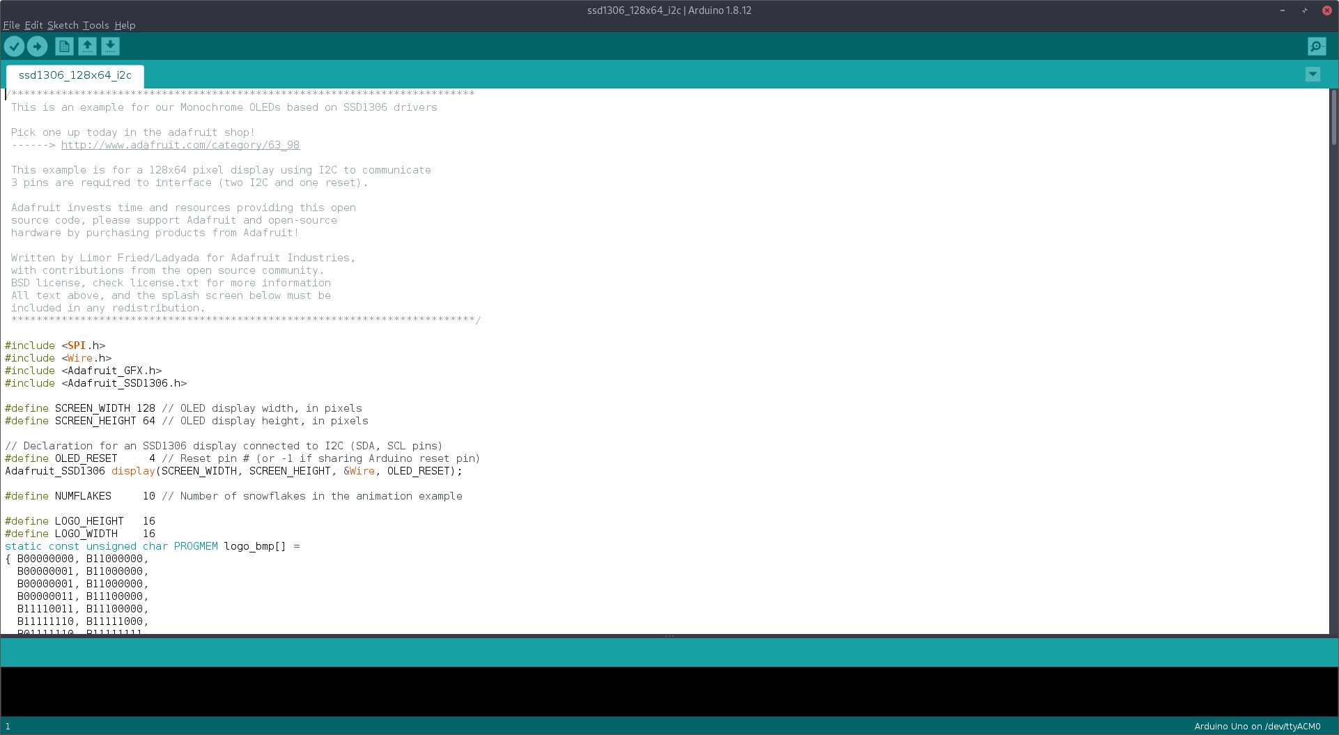
Testing the display
Head to File > Examples > Adafruit SSD1306 > ssd1306_128x64_i2c (choose the size suitable to your display). Once loaded, it should look like this:
If you were to load this example, you would probably (unless you got lucky) find that nothing would happen. That’s because we need to change the address that we discovered earlier. Head down to this section in the code:
 if(!display.begin(SSD1306_SWITCHCAPVCC, 0x3D)) { // Address 0x3D for 128x64
    Serial.println(F("SSD1306 allocation failed"));
    for(;;); // Don't proceed, loop forever
  }
Notice the “0x3D” as the address, change this to the address you discovered earlier, so I would change mine to 0x3C.
You will also want to change this line:
#define OLED_RESET 4To this:
#define OLED_RESET -1Go ahead and then upload.
If everything works correctly, you should now see your display slowly go through and play through different animations and text, like this:
At this point I would now suggest taking a look at how to issue commands to the display and how it works.
The basics
Let’s take a look at one of the functions in the example, find the following function:
void testdrawstyles(void) {
  display.clearDisplay();

  display.setTextSize(1);             // Normal 1:1 pixel scale
  display.setTextColor(SSD1306_WHITE);        // Draw white text
  display.setCursor(0,0);             // Start at top-left corner
  display.println(F("Hello, world!"));

  display.setTextColor(SSD1306_BLACK, SSD1306_WHITE); // Draw 'inverse' text
  display.println(3.141592);

  display.setTextSize(2);             // Draw 2X-scale text
  display.setTextColor(SSD1306_WHITE);
  display.print(F("0x")); display.println(0xDEADBEEF, HEX);

  display.display();
  delay(2000);
}
This is probably the easiest function in all of the examples to understand.
Taking the very first line:
display.clearDisplay();This should be self explanatory but this is used to clear everything that is currently on display.
The next 2 lines are both to do with changing the appearance of the font:
display.setTextSize(1);
display.setTextColor(SSD1306_WHITE);
This allows you to control the size of the text, and also the colour.
Finally we get to actually writing to the display with the next 2 lines:
display.setCursor(0,0);
display.println(F("Hello, world!"));
display.setCursor(0,0) tells the display where to position the cursor before writing. This can be used to offset the text to different positions around the display, perhaps if you want to have text centred for example.
Then you will notice the display.println and the similarities to the Serial.println function. They work pretty much the exact same and is the command that will actually add the text to the display. You can also use display.print(“text”) to add text without a line return at the end if you want to chain together a few commands.
The next few lines are just repeats of the first few lines and demonstrate how to change font size and colour.
The last line is the most crucial one – display.display() is essential if you actually want anything to happen. This is what actually draws the text to the display and makes everything happen. You could do everything above and nothing would happen if you don’t enter display.display().
It’s worth nothing that you can draw to the display after making multiple changes to the display, you do not have to call it after every change until you want it to display on screen.
At this point I’d suggest looking through some of the other functions in the code so you can see how the display is used.
You can also give this example a try:
#include <SPI.h>
#include <Wire.h>
#include <Adafruit_GFX.h>
#include <Adafruit_SSD1306.h>
#define SCREEN_WIDTH 128 // OLED display width, in pixels
#define SCREEN_HEIGHT 64 // OLED display height, in pixels
// Declaration for an SSD1306 display connected to I2C (SDA, SCL pins)
#define OLED_RESET -1 // Reset pin # (or -1 if sharing Arduino reset pin)
Adafruit_SSD1306 display(SCREEN_WIDTH, SCREEN_HEIGHT, &Wire, OLED_RESET);
void setup() {
Serial.begin(9600);
if(!display.begin(SSD1306_SWITCHCAPVCC, 0x3C)) {
Serial.println(F("SSD1306 allocation failed"));
for(;;); // Don't proceed, loop forever
}
display.clearDisplay();
textexample();
}
void loop() {
}
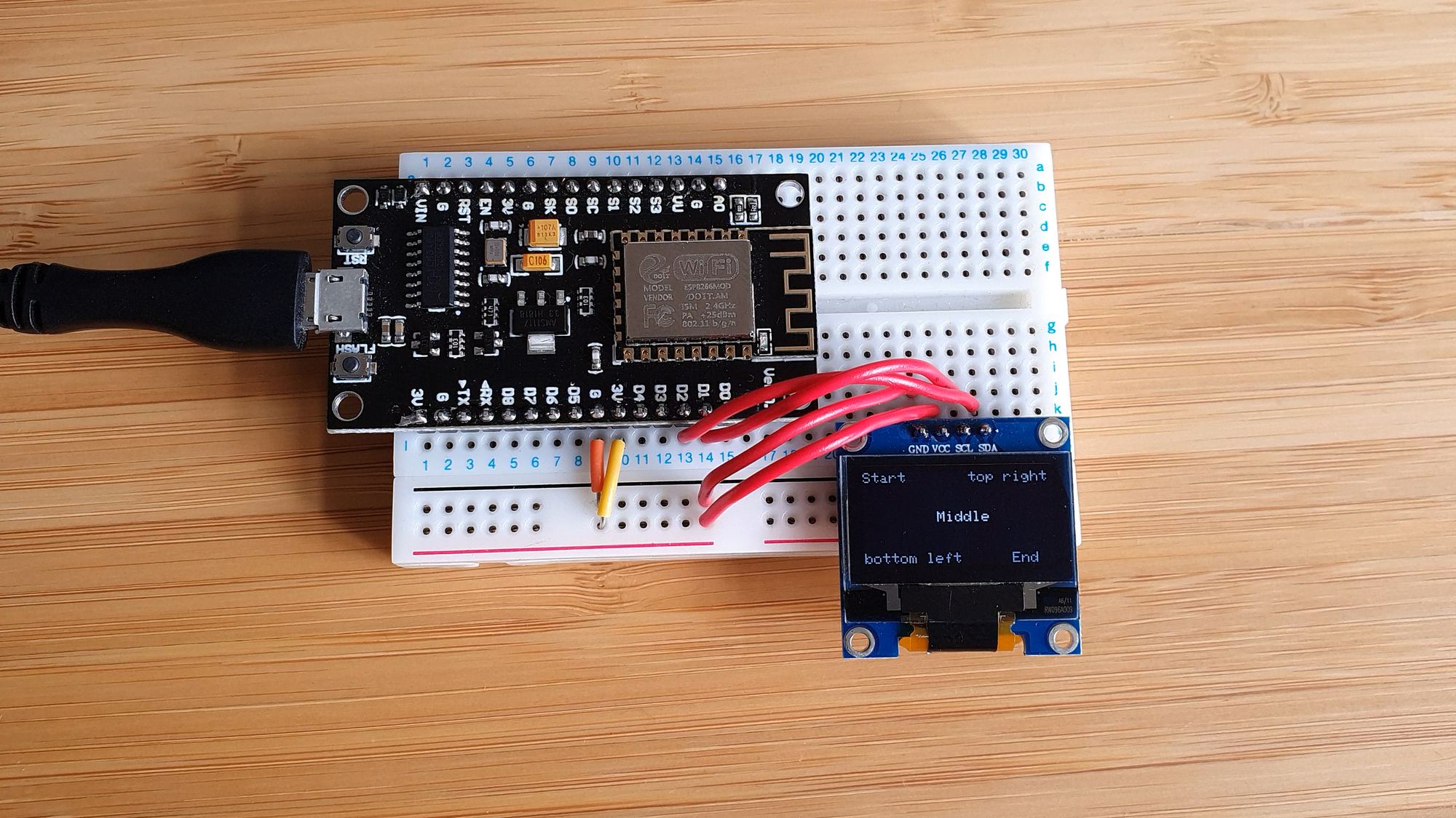
void textexample(void) {
display.clearDisplay();
display.setCursor(0,0);
display.setTextSize(1);
display.setTextColor(SSD1306_WHITE);
display.println("Start");
display.display();
delay(2000);
display.setCursor(50,27);
display.println("Middle");
display.display();
delay(2000);
display.setCursor(100,55);
display.println("End");
display.display();
delay(2000);
display.setCursor(0,55);
display.println("bottom left");
display.display();
delay(2000);
display.setCursor(72,0);
display.println("top right");
display.display();
}
Which demonstrates how to move text around the display at different positions:
Hopefully that makes everything more clear!
Practical example
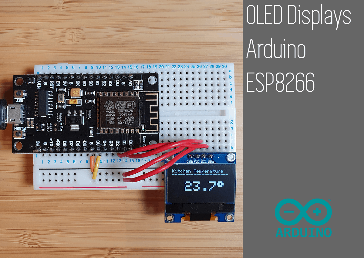
Let’s take a look at a super quick practical example of integrating with an existing project, say you have a temperature sensor like the one we made previously here.
You can imagine with this project, having a display to provide real-time temperature to the user would be extremely beneficial, letting them know instantly, rather than having to pull our your smart phone to see what the temperature is.
By adding just a few lines of code we can clearly display to the user the temperature. Note I have created a temperature “simulator” by generating random numbers, so that you can test it out for yourself:
#include <SPI.h>
#include <Wire.h>
#include <Adafruit_GFX.h>
#include <Adafruit_SSD1306.h>

#define SCREEN_WIDTH 128 // OLED display width, in pixels
#define SCREEN_HEIGHT 64 // OLED display height, in pixels

// Declaration for an SSD1306 display connected to I2C (SDA, SCL pins)
#define OLED_RESET     -1 // Reset pin # (or -1 if sharing Arduino reset pin)
Adafruit_SSD1306 display(SCREEN_WIDTH, SCREEN_HEIGHT, &Wire, OLED_RESET);

void setup() {
  Serial.begin(9600);

  // SSD1306_SWITCHCAPVCC = generate display voltage from 3.3V internally
  if(!display.begin(SSD1306_SWITCHCAPVCC, 0x3C)) { // Address 0x3D for 128x64
    Serial.println(F("SSD1306 allocation failed"));
    for(;;); // Don't proceed, loop forever
  }

  // Clear the buffer
  display.clearDisplay();
  display.display();

}

void loop() {

  float mainTemp = random(18, 25);
  float decimalTemp = random(0,99) / 100.0;
  float temp = mainTemp + decimalTemp;
  displayTemp(temp);
  delay(2000);

}

void displayTemp(float temp) {
  display.clearDisplay();
  display.display();

  display.setTextSize(1);
  display.setTextColor(SSD1306_WHITE);
  display.setCursor(0,0);
  display.println("Kitchen Temperature");
  display.println("---------------------");
  display.setCursor(28,27);
  display.setTextSize(3);
  display.print(temp, 1);
  display.print((char)247);
  display.display();
}
And now the display updates the temperature every couple of seconds like so:
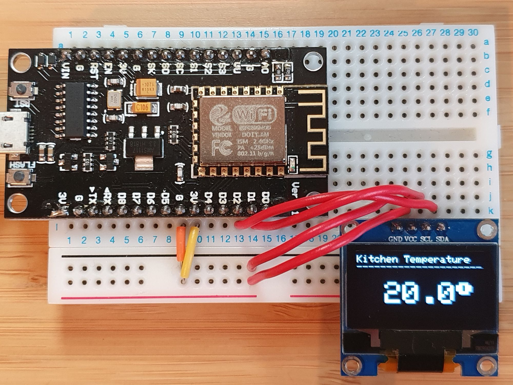
Obviously there is way to make this look much prettier, but this is a really functional way to add some basic information to your project. The best thing is that it doesn’t require massive amounts of code change to get it to work, just a few simple additions and you are done.
Conclusion
You can see just how easy it is to add a functional information display to any existing project with just a few tweaks using the SSD1306 OLED library. For some projects like a temperature sensor, fingerprint scanner or even a power meter I think the information you can get is really invaluable!