DIY Philips Hue LED Strips - Installing ESPHome on Magic Home RGBW controllers

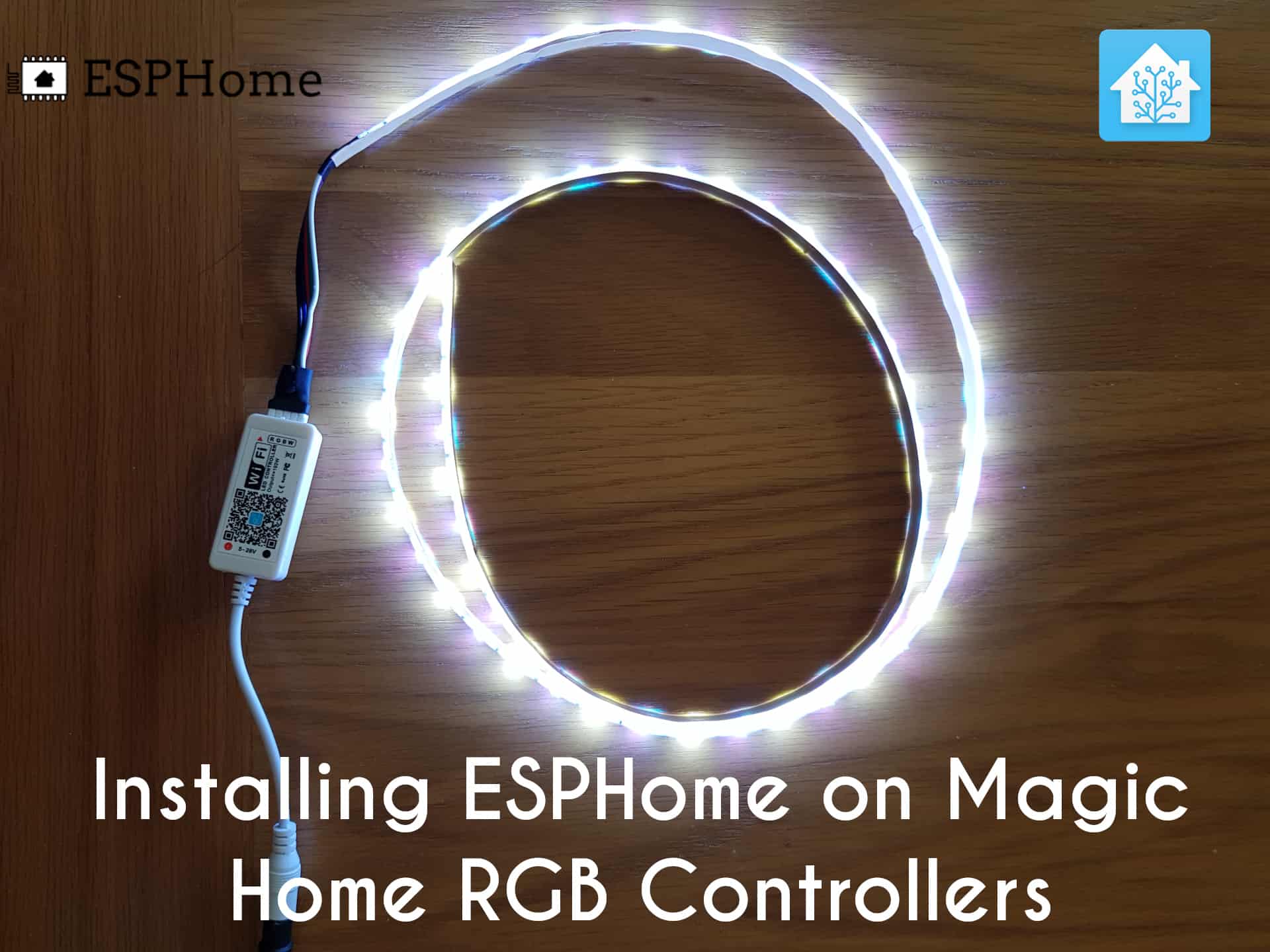
Following on from our last post about installing ESPHome on cheap smart bulbs from Amazon, this time we are going to take cheap RGBW controllers and LED strips and install ESPHome on them to add to our Home Assistant integration, expanding our DIY Philips Hue setup.
The Philips Hue RGB strips are incredibly expensive. Once again, I’d like to stress that they are fantastically easy to set up. For someone not interested in tech in the slightest, they make a ton of sense and they just work. However they aren’t accessible for everyone given the price point.
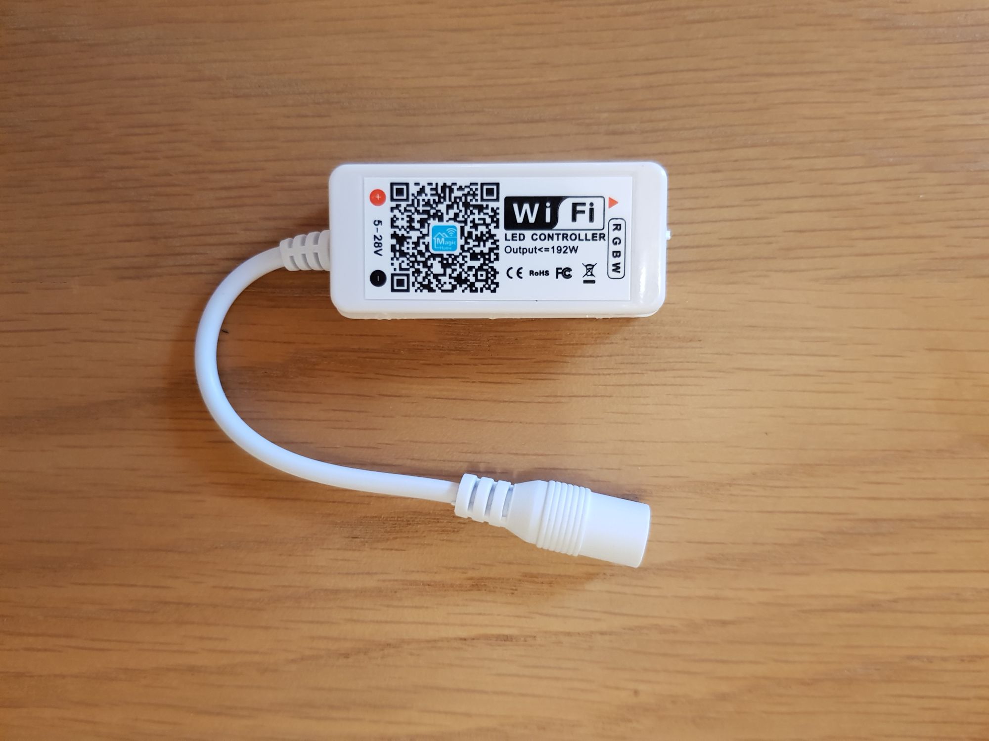
Enter the “Magic Home” RGB controllers which can be found easily on Amazon, Ebay, Ali-express etc. These are ESP8266 boards inside and are super easy to work on, and with a little tinkering can be easily integrated into Home Assistant using ESPHome giving us full control over our LED strips. Of course it is an ESP8266 so you can use Tasmota or any other compatible firmware.
Guide:
Parts List:
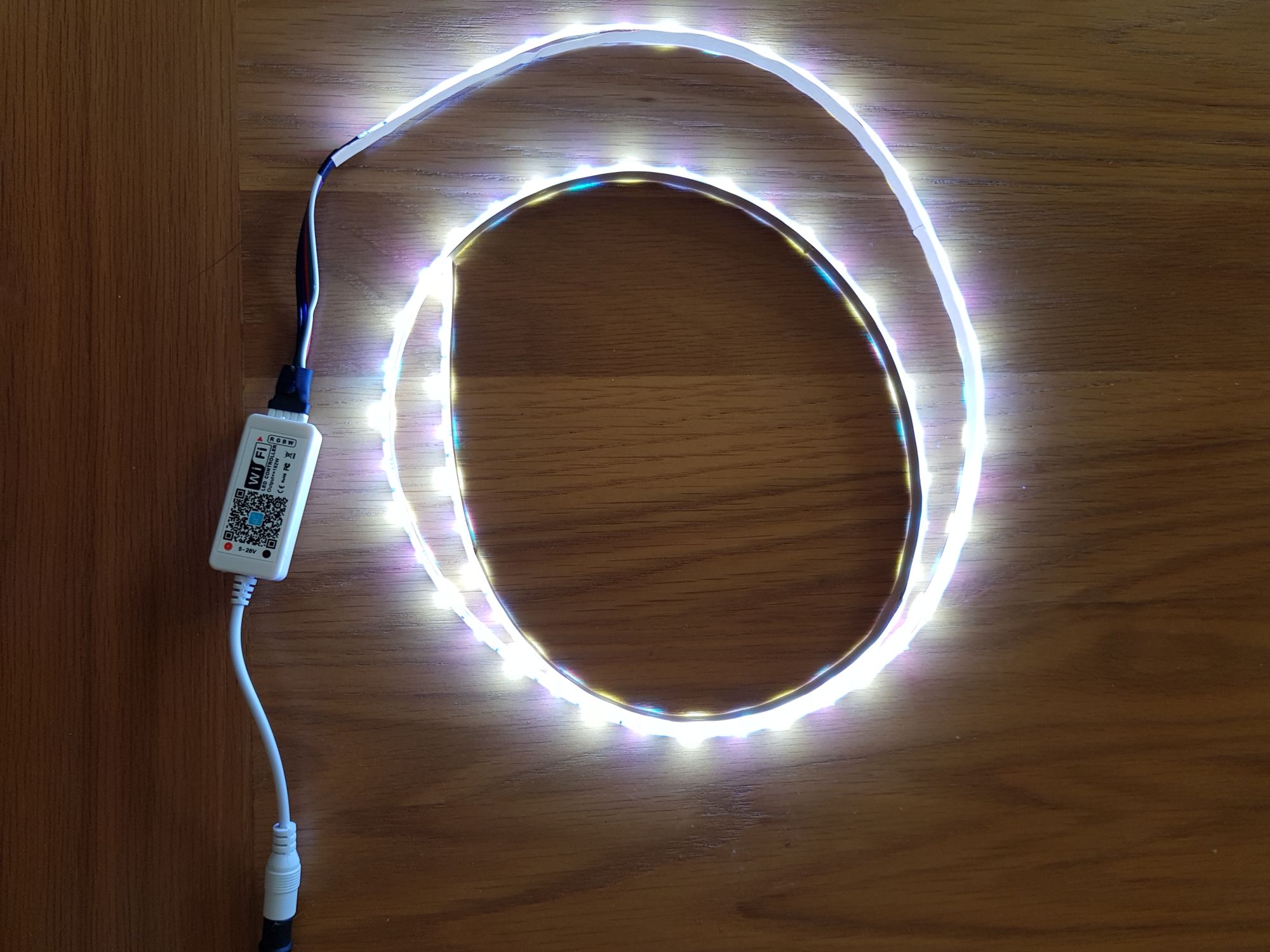
- RGBW Controller – I opted for a non remote version
- RGBW LED Strips
- Power Supply – 12v DC power supply with barrel jack
- FTDI serial adapter
I went for an RGBW version, meaning RGB + white, you can get just RGB version if you don’t want white, or you can get an RGBWW version which gives you cool + warm white. Just make sure your LED strip and controller match, so same version of both.
I also went for the non IR remote version of the controller, since I don’t have a need for the remote control.
You might already have a power supply already, these are used for loads of things. Just make sure it is 12-18v DC.
Preparation:
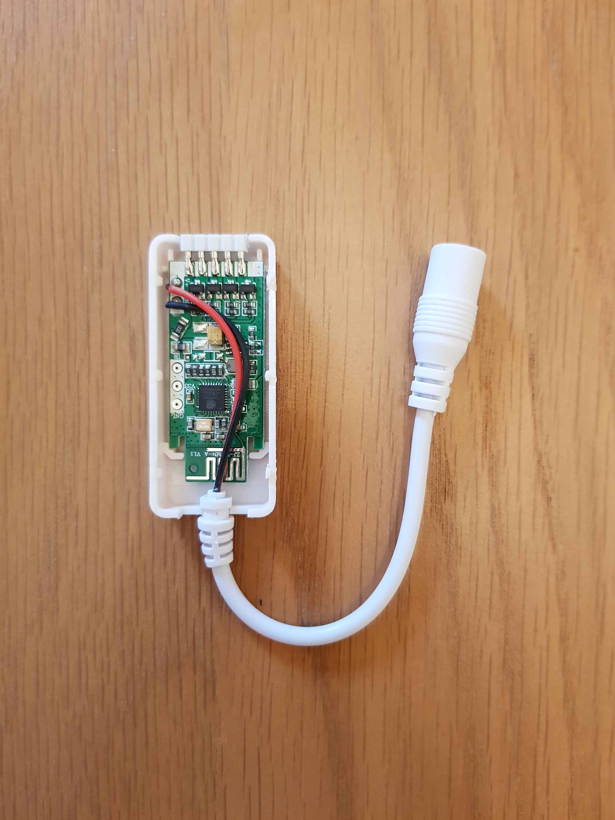
Firstly we need to open up our controller, this is done very easily by gently prising around the edges to split apart. Once open, we can see we have an ESP8285 controller inside:
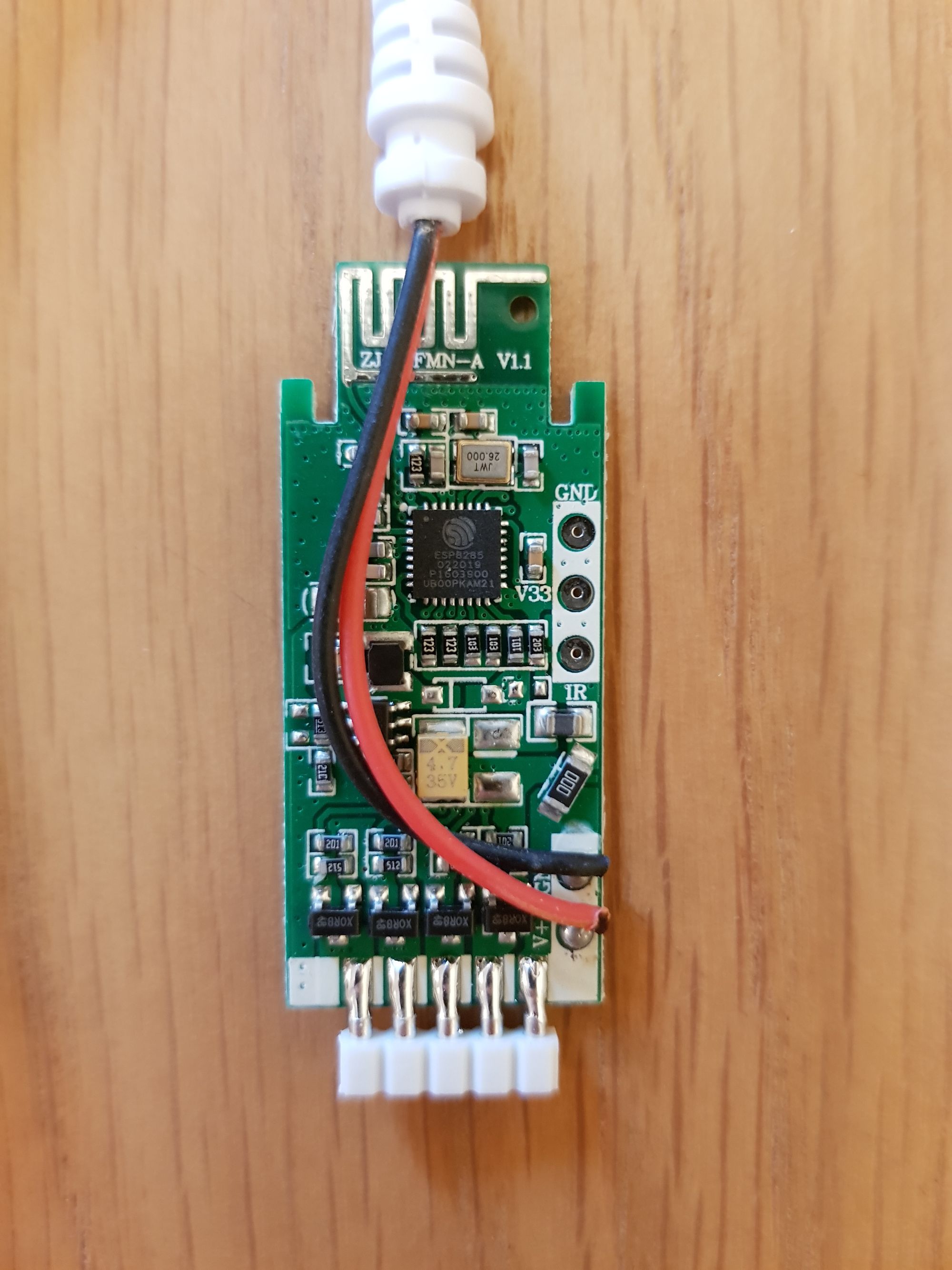
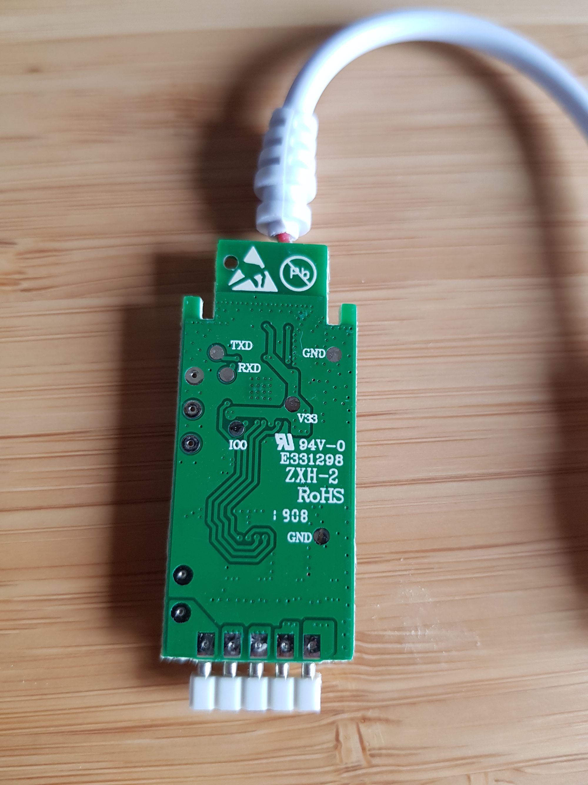
Next we need to identify our connections:
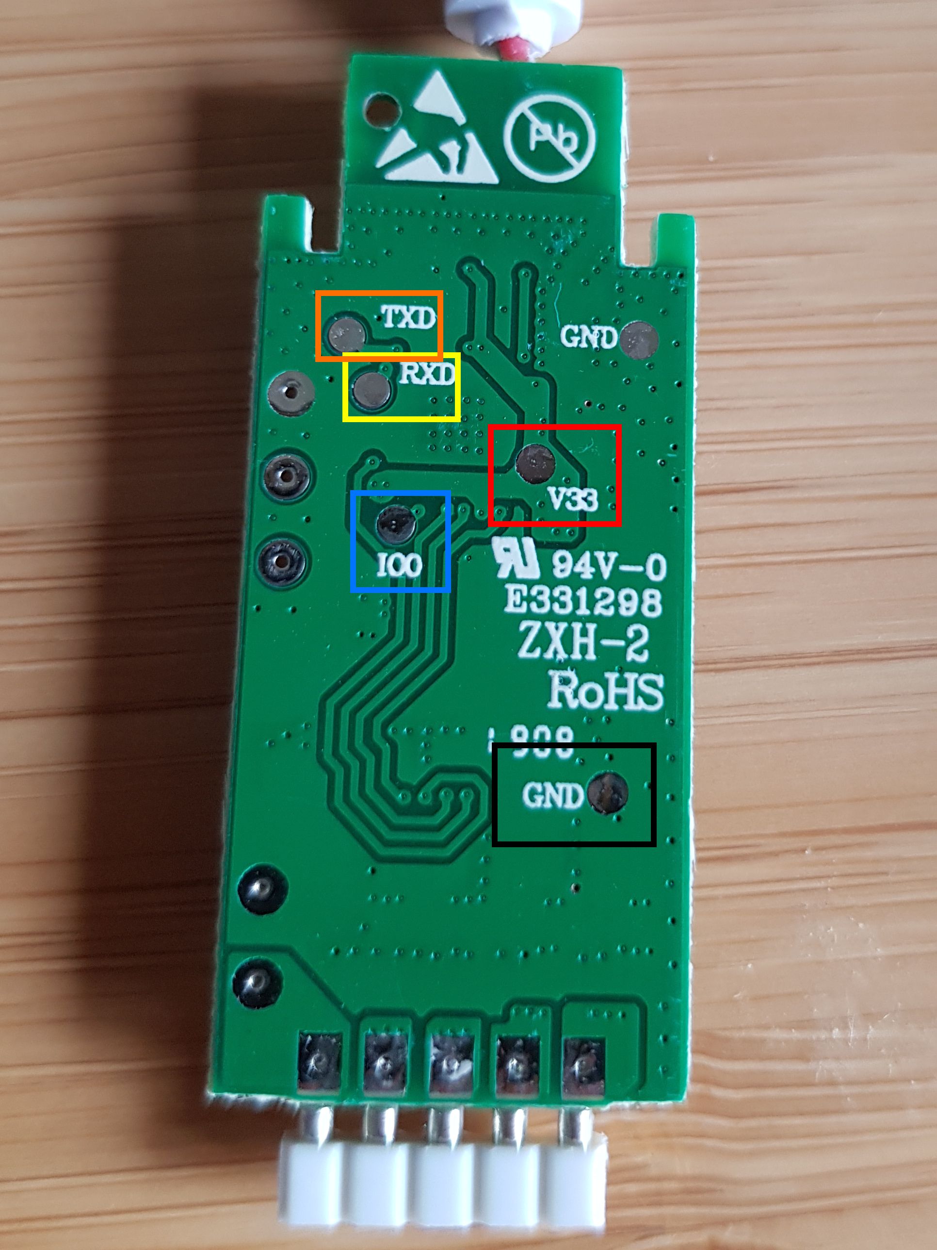
These are fairly easy to solder and should be pretty straight forward.
Next, take your FTDI serial adaptor and wire it as follows:
It should hopefully look something like this, hopefully neater than my 2 minute rush job:
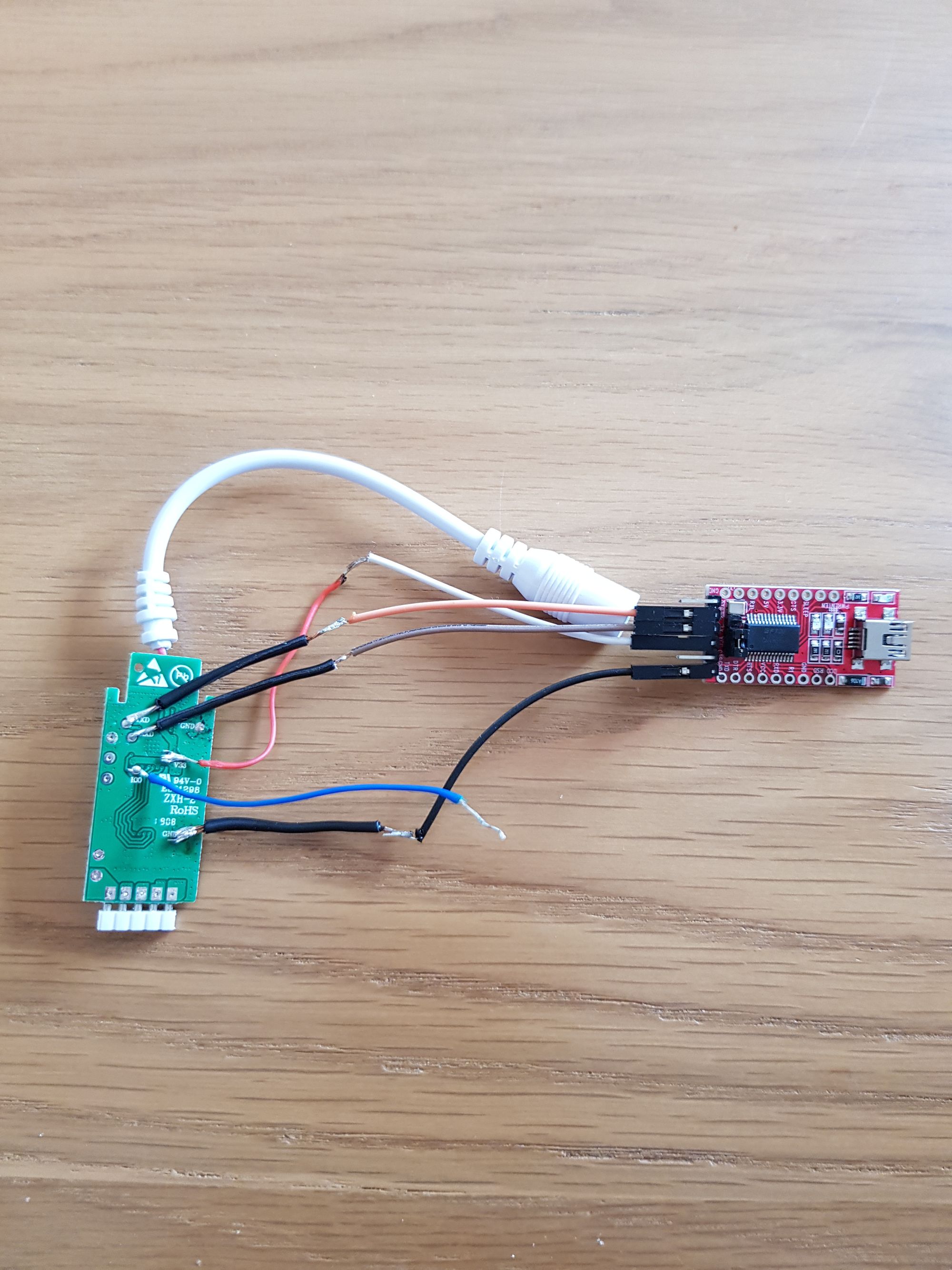
Note you will see I have my IO0 connection not connected, this is because I am simply holding this to ground as I insert my USB, this is all that is required to enter flash mode.
Importantly, ensure that your USB to serial adaptor is set to 3.3v.
Now we need to create the ESPHome firmware to load onto our controllers and LED strips.
Creating firmware
Creating firmware is pretty straight forward. For this article, I’ve created an example file for you, but if you want to follow through the wizard then please follow our example from the previous example.
So create a new yaml file and give it a sensible name, mine is called “livingroom-strip.yaml”. Paste the following into the file:
esphome:
  name: node_name
  platform: ESP8266
  board: esp8285

wifi:
  ssid: "Your SSID Here"
  password: "Your Wifi Password"

# Enable logging
logger:

# Enable Home Assistant API
api:
  password: "Your API Password"

ota:
  password: "Your OTA Password"

light:
  - platform: rgbw
    name: Nice Friendly Name
    red: pwm_r
    green: pwm_g
    blue: pwm_b
    white: pwm_w
    restore_mode: ALWAYS_ON

output:
  - platform: esp8266_pwm
    pin: GPIO12
    frequency: 1000 Hz
    id: pwm_r

  - platform: esp8266_pwm
    pin: GPIO5
    frequency: 1000 Hz
    id: pwm_g

  - platform: esp8266_pwm
    pin: GPIO13
    frequency: 1000 Hz
    id: pwm_b

  - platform: esp8266_pwm
    pin: GPIO15
    frequency: 1000 Hz
    id: pwm_w
Fill out the details relevant to your network, including node name, Wifi SSID, Wifi Password, API password, OTA password and friendly name. Indentation is important in these YAML files so be aware of that.
You should now have a valid YAML file!
Flashing
Once again, ensure your USB to serial adaptor is set to 3.3v, this would also be a good time to just recheck your connections as above.
Plug in one end of your USB connection with the other left out. Go ahead and grab your IO0 wire and hold it onto your ground connection. While doing that, plug the other end of the USB cable in. After a couple seconds you can let go of the IO0 to ground wire.
Once done, you can then go ahead and run the following command which will instruct ESPHome to compile:
esphome your-yaml-file.yaml runThis will take a minute or two to complete, at which point you will then be asked how you want to upload. Select the option for serial and it should begin to upload.
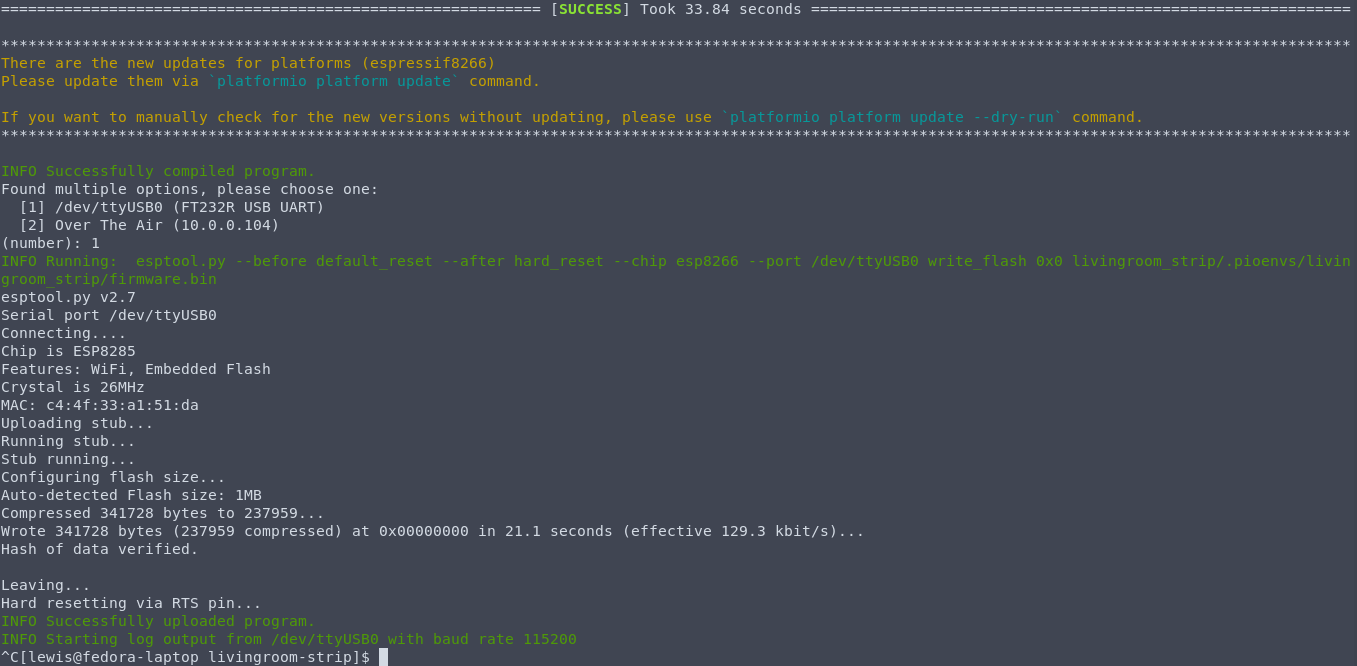
Assuming everything was successful, you can now disconnect everything from the USB adaptor.
Now would be a great time to take it for a test spin! With everything disconnected from serial adaptor, you can now plug the DC power supply into the Magic Home. Then plug your LED strip into the Magic Home and switch on. If done correctly, the LEDs should light up straight away, since we have set restore mode to always on. If nothing happens, flip the LED strip connector around, its easy to put this in the wrong way round. Don’t worry, nothing will break by doing this!
Final Steps
With everything working correctly, we now just need to de-solder the wires from our board, this should be very straight forward.
Re-fit the esp8266 into the plastic casing, make sure to get the orientation the right way round.
Go ahead and connect everything again and test just to ensure. It is now ready for you to fit in its final position.
If you have the discovery component setup in Home Assistant, your ESPHome enabled LED strips will show right up in the Notifications section.